About the Customize tab
The Customize tab contains all the editing and correction tools in DxO PhotoLab.
In this chapter, you will discover and learn all the tools, as they are arranged when you use the DxO Advanced workspace.
Left pane
The left pane of the Customize tab contains the following palettes (top to bottom):
- Histogram
- Move/Zoom
- History
- Preset Editor
Histogram
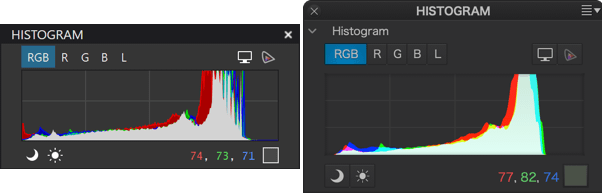
The histogram shows, color by color, how many pixels there are for each level of luminance.
The three color channels (RGB) and the Luminance channel can be displayed separately (Left: PC, right: Mac).
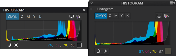
This shows the histogram of an image with a CMYK profile, indicating the luminance levels in the Cyan, Magenta, Yellow and Black channels.
About the histogram
The histogram is the most convenient way to determine how an image has been exposed, in order to correct it effectively. In simple terms, the histogram is a graph showing the number of pixels per brightness level: the larger a vertical line, the more pixels there are at that brightness level. If the histogram is shifted to the right, the image is brighter and, conversely, the more it is shifted to the left, the darker it is. When the histogram is well spread out from left to right, with a nice peak in the center (corresponding to the midtones), the exposure can be considered balanced, with a wide dynamic range.
RGB and L channels
The histogram tool calculates the brightness values for each color channel, and displays them all together on the same chart. However, you can also display the values per channel, as your camera does, by clicking on one of the buttons located on the right side of the chart:
- RGB : displays all the channels simultaneously (RGB and Luminance).
- R, G, or B: Displays the Red, Green or Blue channels accordingly.
- L: Displays the global Luminance channel
The palette displays the characteristics of the area, above the histogram, when you move the mouse pointer over the image. The exact color of this small area is duplicated and magnified in a square tile, next to which its RGB (red, green, blue) primary color composition, each on a scale from 0 to 255, is displayed.
CMYK channels
The DxO PhotoLab histogram also calculates and indicates the distribution of brightness values for each channel of an image with a CMYK profile (cyan, magenta, yellow and black). You can view channels individually, using the corresponding buttons located in the palette (above the histogram on PC, under the histogram on Mac):
- CMYK: display all 4 channels simultaneously.
- C, M, Y or K: displays only the selected channel.
Clipping
When a luminance level goes below the left end of the histogram – the so-called black point, or above the right end – the white point, it will be constrained to pure black or pure white. Pixels in this position, or close to it, are said to be “clipped.” Of course, it is highly desirable to avoid this situation and retain the details in these areas of the image. For this purpose, the DxO PhotoLab histogram offers two tools, represented by two icons located under the histogram:
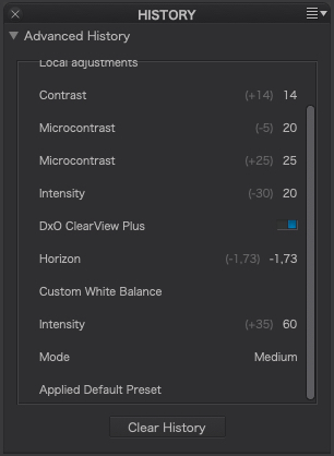
- Shadow clipping: Clicking on the icon will display, in false colors, the zones where no (or only some) information is left in the dark area’s color channels.
- Highlight clipping: Clicking on this icon displays clipped or close-to-clipped bright areas.
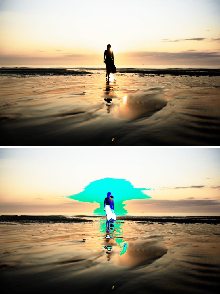
When all color channels are affected, the affected area will be displayed as black; if information is still available in one of the channels, the relevant areas will be displayed in false colors.
Move/Zoom
The palette allows you to navigate the image after zooming in, using a rectangle that you can move with the mouse in the preview. The rectangle represents exactly what you see in the Viewer, and the display is synchronized with the movements of the rectangle.
History
Purpose and function
Located in the left pane of the Customize tab, the Advanced History palette displays all the steps in the work and corrections made to an image, including the date it was opened in the program and the application of default automatic corrections, in ascending chronological order (most recent step at the top). All this information is stored in real time in the DxO PhotoLab database, and requires no intervention on your part.
Use
Depending on the user, the history has a number of uses:
- Listing all corrections of all images for reference.
- Enabling comparison between one image to another by comparing histories.
- Performing before/after comparisons at all stages of correction, for example, to find the most appropriate settings for a particular tool or combination of tools.
The nature of the recorded information
The DxO Advanced History palette records the following information, which is retained when you exit the program (Mac only):
- The default preset that was applied when you opened the image in PhotoLab.
- Name and (ON or OFF) status of the sub-palette used.
- Name of the tool used.
- Current and previous settings.
- The settings of a Custom Presets, grouped and presented in a list (click the step arrow to reveal the settings).
Limiting the number of steps (Mac)
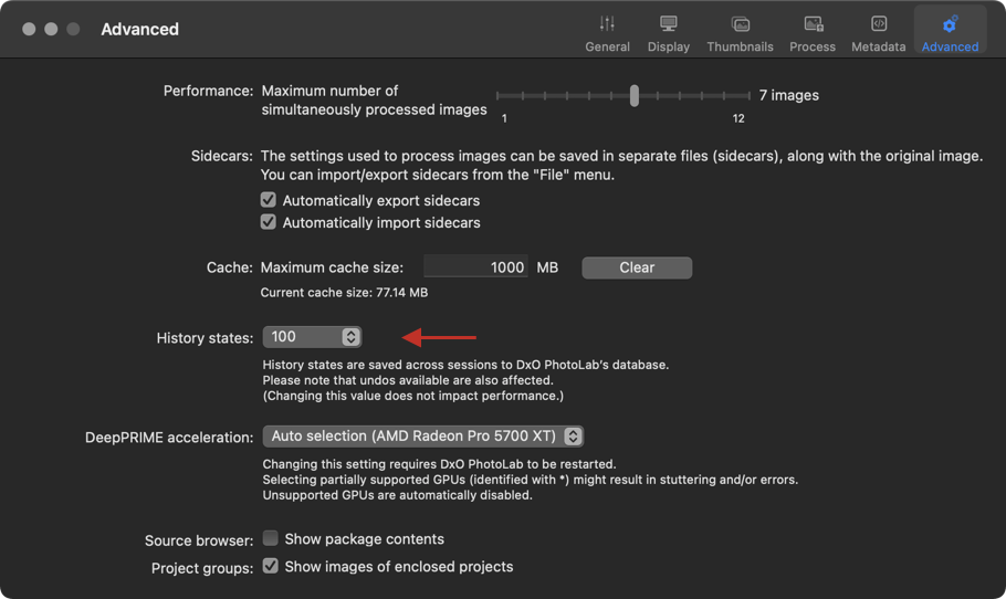
The history recorded in the DxO PhotoLab database represents a negligible amount of information in terms of impact on the program’s reactivity. However, on a Mac, you can limit the number of steps in Preferences > Advanced tab > History states section. By default, the number of entries is set to 100, and the available values range from 10 to Unlimited.
Using the History palette
Going back in the history and comparing
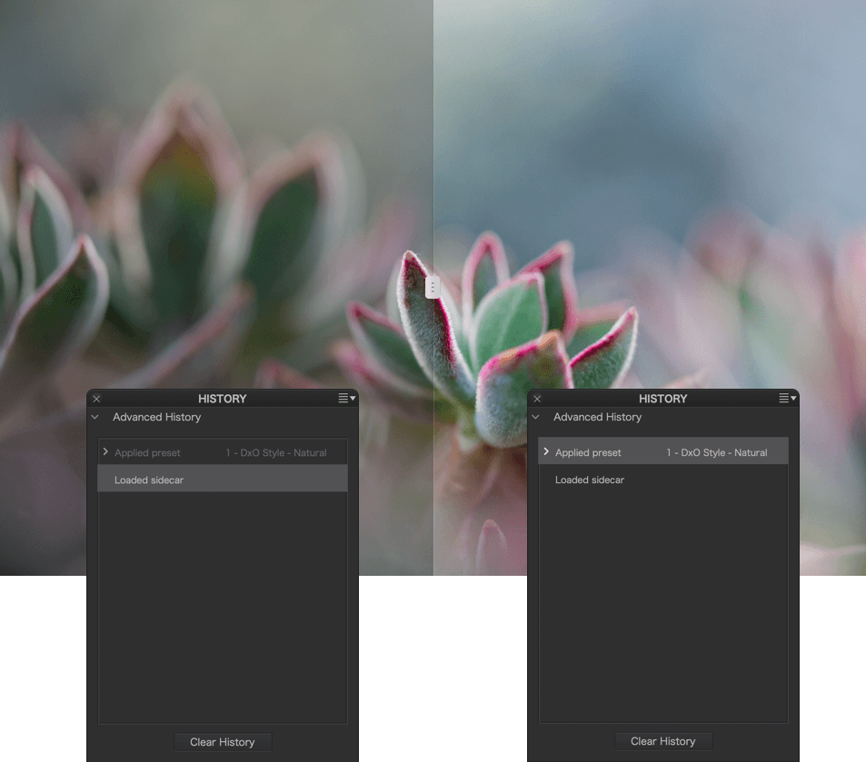
To see the state of an image at a particular stage of correction, scroll through the Advanced History palette and click on a step: the image returns to the precise state it was in at that stage of correction, and the sub-palettes and tools concerned show the settings and values used at that time. Click on a newer or older step, go back in time through the various stages of tool use, and see how the image looks in real time in the Viewer.
Erasing the history (Mac)
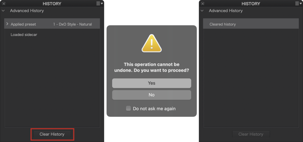
You can’t erase just one or more steps in the history, simply because doing so doesn’t make sense, as corrections are usually made relative to each other (for example, you do the white balance before correcting colors, and erasing the white balance step would not make sense).
If you want to take back a correction, simply act on the tool concerned, by changing its setting or value. In this case, this action will appear at the top of the history.
However, you can erase the whole history. At the very bottom of the History palette, click on Clear History. A dialog box will warn you that the operation is irreversible and, after clicking OK, the contents of the palette will be cleared, only one step (“Clear History”) is displayed.
Important: Deleting the history does not delete or reset your corrections and settings!
Of course, after you have erased the history, it starts saving again as soon as you apply new corrections to the image. In this case, the displayed values and settings start again from this step onwards; the corrections you erased from the history stay erased.
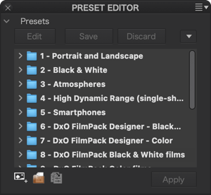
Presets Editor & Presets
About DxO PhotoLab presets
A preset is a set of corrections that you can apply in one go to any pictures in DxO PhotoLab. The goal of the presets is to help you to record and keep track of your favorite corrections, and to ease and accelerate your workflow within the application.
There are two kinds of presets in DxO PhotoLab:
- Full presets cover all the existing corrections available in the Customize tab, meaning that each correction has a status of either activated (with defined setting parameters) or deactivated.
- Partial presets, on the other hand, cover only a limited number of corrections among all existing corrections, with the status of some corrections remaining undefined.
As soon as you open an image in DxO PhotoLab, the default full preset DxO Style – Natural is automatically applied. You can choose a different preset as the default if desired.
The different categories of available presets
DxO PhotoLab offers a set of full presets divided into 1 + 10 categories:
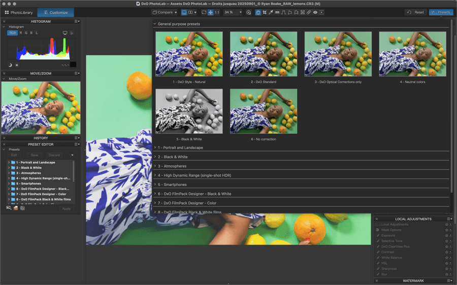
General purpose presets
The General use category includes six presets:
- DxO Style – Natural, the preset systematically applied by default to your images, as soon as you open their respective folders in the Source Browser. It includes the following corrections :
- DxO Smart Lighting on Custom mode (Intensity 15).
- Selective Tone (Highlights -15, Midtones 18, Shadows 10, Blacks 0).
- DxO ClearView Plus (Intensity 10).
- Contrast set to 10.
- Vignetting on Auto.
- Color rendering unchanged for JPEGs, Generic rendering for RAW files.
- Protection of saturated colors on Auto.
- HSL, Saturation & Vibrancy sliders set to 5.
- DxO Denoising Technologies set on High Quality and Auto.
- Lens Sharpness Optimization, Global slider on +1,00, and both the Details and the Bokeh sliders set to 50 (or Sharpness Mask default settings, if a DxO Module is not available).
- Distortion on Auto.
- DxO Standard, which was the default preset prior to DxO PhotoLab 7 (Sept. 2023). It includes the following corrections:
- DxO Smart Lighting on Slight mode.
- Color rendering unchanged for JPEGs, camera default rendering for RAW files.
- Protection of saturated colors on Auto.
- Noise reduction on Auto.
- Distortion on Auto.
- Vignetting on Auto.
- Chromatic aberration on Auto (and lateral chromatic aberration correction activated).
- Lens Sharpness Optimization, Global slider on +1,00, and both the Details and the Bokeh sliders set to 50 (or Sharpness Mask default settings, if a DxO Module is not available).
- Neutral colors are identical to DxO Standard, except that the colors are less saturated and the contrast is less pronounced.
- Optical corrections only, applies only the DxO Module corrections.
- Black & White automatically converts a color image based on its content.
- No correction deactivates all of the corrections in DxO PhotoLab, so images are displayed “as shot.” In the case of RAW files, DxO PhotoLab still performs demosaicing using all of the basic settings that are optimal for your camera.
You can change the default preset in Preferences. The new default preset will be applied only to images that you process after making the change, not to images that were already opened with the previous or original default preset.
Portrait and Landscape
The Portrait and Landscape category is composed of two groups of presets that have been designed for these two uses. For portraits, for example, the contrast is softer and the skin tones have been optimized, whereas for landscapes, the contrast and the colors have greater emphasis. The following eight presets are available in this category:
- Portrait – Standard
- Portrait – Bright
- Portrait – Candy colors
- Portrait – High key
- Landscape – Standard
- Landscape – Polarized postcard
- Landscape – Contrasty
- Landscape – Washed out
Black & White
The Black & White category also provides eight presets that let you modify your images by playing with the contrast. You will find here presets that are adapted for “him” and “her” portraiture and for landscapes; presets that produce highly detailed images, and others which are shrouded to give a dream-like effect. Of course, all of these presets can be applied to any subject:
- B&W – Dense.
- B&W – Structured.
- B&W – Dramatic skies.
- B&W – Low key.
- B&W – For her.
- B&W – For him.
- B&W – Subdued.
- B&W – Veiled.
Atmospheres
The Atmospheres category offers eight creative presets based on toning. They can be applied to both color and black & white images:
- Mist
- London night
- Blue hour
- Twilight
- Old film
- Polar
- Heather purple
- Old school
High Dynamic Range (single-shot HDR)
This category contains four presets that simulate HDR effects – that is, images with an extended dynamic range but with a tonal range that is redistributed to be used without having to use special software or 32-bit files. These single-shot image presets do not require combining multiple images shot at different exposures, and can be used on both RAW and JPEG files:
- HDR – Realistic: Provides a less-pronounced HDR effect. Restores highlights, lightens shadows, and has a reasonable effect on the tone curve and vibrancy.
- HDR – Artistic: Provides a marked HDR effect. Restores highlights, strongly brightens shadows, and emphasizes the tone curve and vibrancy.
- HDR – Backlight correction: strongly lightens shadows under backlighting conditions, while still preserving a natural look.
- HDR – Black & White: optimized for monochrome images. Strongly accentuates contrast.
Smartphones
This category contains two presets that have been optimized for images taken with mobile phones.
- Smartphones – Low ISO
- Smartphones – High ISO
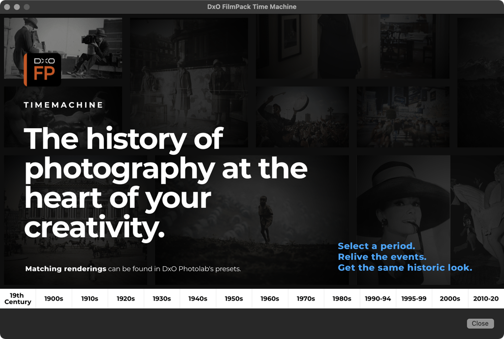
DxO FilmPack Designer – Black and White/Color/Black & White films/Color films and DxO FilmPack Time Machine
Designer presets, available when DxO FilmPack is installed, are based on film renderings and graphic effects – filters, toning, vignetting, textures, defects – that bring a new artistic dimension to your images.
Time Machine presets are installed from DxO FilmPack 6 onwards, and offer you film renderings from 1827 to 2019, the history of which you can consult via the Time Machine function.
Designer renderings are available from DxO FilmPack 4 or DxO FilmPack 5.
Time Machines renderings are available from DxO FilmPack 6.
They appear automatically when activating DxO FilmPack (a license is required).
Applying a preset
Applying a predefined preset
To apply a preset to your image, click on the Presets (Mac) / Apply a preset (PC) button in the command bar. Doing so opens a window in which all of the available presets and their effects on the selected image appear.
You can also right-click on a thumbnail in the Image Browser and select Apply Preset in the context menu, or click on the preset of your choice in the list in the Preset Editor.
Combining presets
You can use more than one preset on an image. If each preset has a different value for the same correction, the rule is simple: The values of the last applied preset take precedence; for example:
- If the first-applied preset gives a value of Disabled for a correction, and the second preset gives the value of Enabled to the same correction, the correction will be Enabled (that is, active).
- If both corrections are set to Enabled, with the first preset supplying a value of, say, “-2,” and the second preset supplying a value of “+1,” then the correction value will be “+1.”
This rule in particular makes it possible to create partial presets that are based on a limited range of corrections to be applied on top of “overall” (or full) presets. When a correction is assigned a value by the partial preset, it will be governed by it. When there is no value assigned to a correction by the partial preset, the correction will be governed by the underlying full preset.
Creating a full preset from current settings
To create a preset from current settings:
- Correcting your image.
- When you are satisfied with the results, right-click on the image thumbnail in the Image Browser, and select Create preset from current settings in the context menu.
- Enter a name for your preset in the dialogue box and click on Save.
- The new preset will appear in the Visual Presets window and in the list in the Preset Editor.
Any preset that you create in this manner will affect all setting values, as it is a full preset.
Managing presets with the Preset Editor (ELITE Edition)
The Preset Editor is a palette in the Customize tab that lets you create and manage your own custom presets, including those that you create “from scratch,” and others that you can create by modifying existing presets.
Preset Editor commands
PC
The Preset Editor lets you create a preset by defining each correction setting:
- New preset group: Creates a folder in which you can group similar presets: by type of camera used, landscape rendering, portrait, etc. (You can use drag and drop to move presets from one folder to another.)
- New preset from current settings: Lets you create a preset from the corrections you have made on the image displayed.
- Copy: easily create a preset from an existing preset.
- Delete: Deletes the selected preset or folder.
- Import: Lets you import presets from an older version of DxO PhotoLab or created on a different computer.
- Export: enables the sharing of a preset by exporting it to a folder on the hard drive.
- Edit: Lets you modify a preset (ELITE Edition).
- Apply: Lets you apply the preset to the selected image.
- Save: Lets you save changes to a preset (this command appears only in Edit mode).
- Cancel: Returns a preset to its initial saved settings (this command appears only in Edit mode).
- New empty preset (only from the context menu and only in the ELITE edition): Creates an empty preset that contains no settings. The preset is created in a folder that you choose in advance.
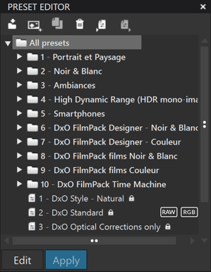
DxO PhotoLab provides some locked presets (marked with a padlock icon) so you cannot modify or delete them.
You can create as many presets as you want and save them in custom folders, import them into other sessions or versions of DxO PhotoLab, and export them to share them with other users.
To verify or to change a preset’s settings, select it in the Preset Editor and then click on Edit: the relevant palettes will then be displayed in edit mode.
Mac
- New preset from current settings: Lets you create a preset from the corrections you have made on the displayed image.
- New group creates a folder in which you can group similar presets.
- Duplicate selected preset lets you create a preset from an existing preset.
- New empty preset (only from the context menu and in the ELITE edition): Creates an empty preset that contains no settings. The preset is created in a folder that you choose in advance.
A drop-down menu located in the upper right corner of the palette offers the following commands (also available in the editor by right- clicking on the preset): New preset from current settings, New empty preset, New group, Duplicate preset, Rename, Delete, Apply preset, Edit preset, Save, Save copy, Cancel changes, Import [note that importing several presets simultaneously is possible], and Export.
Modifying a preset from an existing preset (ELITE Edition)
PC and Mac
To change an existing preset:
- Click on the preset that you want to change.
- Click on the Edit button on the top left of the Preset Editor palette. The relevant correction palette tools will switch to editing mode (indicated by blue banding on the left edge of the palettes).
- Uncheck the settings in the palettes that you want to deactivate, or modify the setting parameters as desired. You can expand the hidden palettes to activate, deactivate, or modify their settings.
- When you are finished making all the changes to the settings, click on the Save button in the Preset Editor palette.
- Click again on the Edit button to quit the create/edit preset mode.
To create a variant of a locked DxO preset, click on the Copy button in the command bar of the Preset Editor and then rename the copy.
In all cases, changes to preset parameters can be canceled either by selecting Undo in the Edit menu or by using the Ctrl (PC) / Cmd (Mac) + Z keyboard shortcut.
Preset folders (ELITE Edition)
You can open folders in the preset folder list by either double-clicking on them, or by a single click on the arrow on the top left. Clicking on the name of a folder lets you rename it, just like the way you rename a file. To rename a folder, just click on its name. You should give your folders relevant names in order to efficiently organize and classify your presets.
Right pane
The right pane of the Customize tab contains the following palettes (top to bottom):
- Light
- Color
- Detail
- Geometry
- Local adjustments
- Watermark
- DxO ViewPoint (if installed).
- DxO FilmPack (if installed).
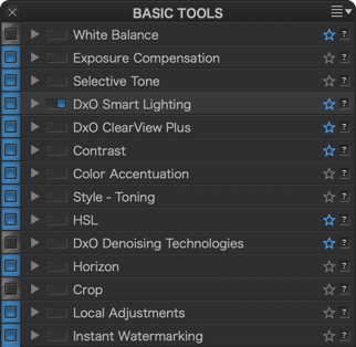
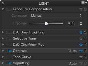
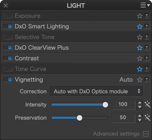
The Light palette
Exposure
About Exposure
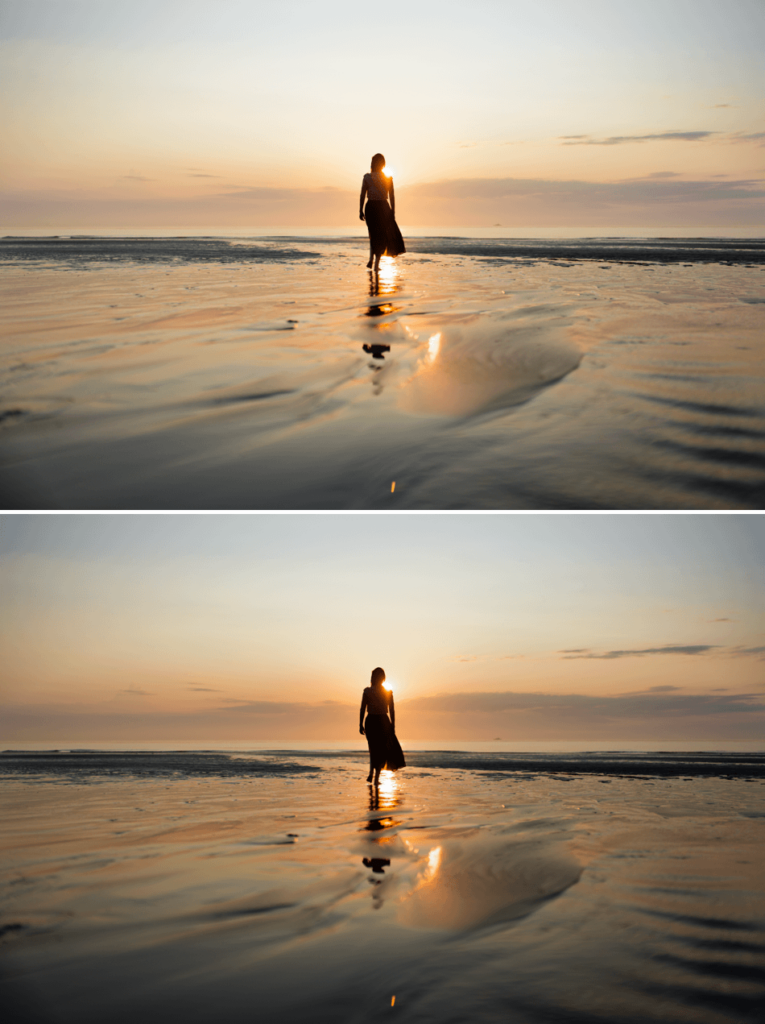
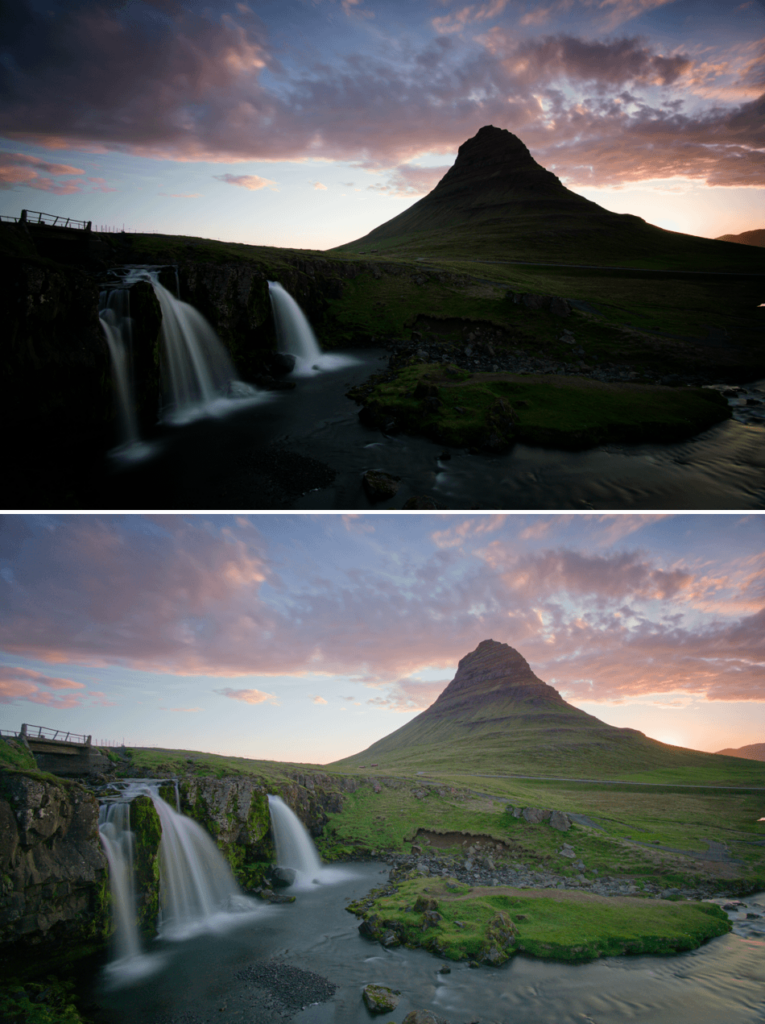
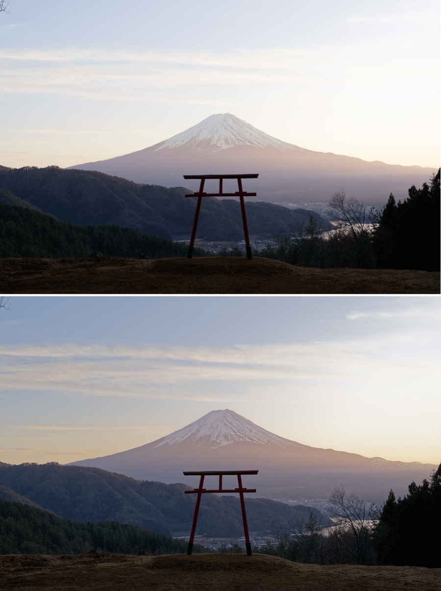
The image on the bottom shows the result achieved with “Highlight Priority – Strong” in the Exposure palette.
Exposure adjusts the image exposure level— that is, it increases or reduces the brightness coefficient of each pixel in the image. Because photographic systems record a reduced range of luminosities, in all cases of an inferior range to that offered by nature, most photos exhibit over- or under- exposed areas, or both at once.
Overexposure presents the biggest problem in digital photography, since a saturated camera sensor cannot cope with brightness above a certain level and returns all-white pixels. The Exposure tool can often recover information in these areas that have been incorrectly exposed, particularly with respect to RAW images, whose color channels generally retain some information even for burnt areas. With JPEG images, which have already undergone a series of in-camera processes relative to each RGB channel, however, highlights that are lost are gone for good.
Correcting a RAW file
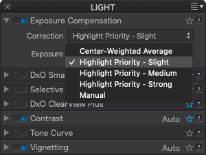
The Correction drop-down menu, specific to RAW-format images, proposes five automatic correction modes and one manual option:
- The Center-weighted average option: Optimizes the correction process (exposure adjustment) at the center of the image.
- Highlight Priority automatic modes: Deals with highlights at three different levels of recovery: slight, medium, and strong. Whichever correction you choose, be sure to verify the results in the histogram.
- Manual (correction by default when Exposure is activated): Requires the use of the Exposure slider, which has a range from –4 Ev to +4 Ev (1 Ev, or “exposure value,” is the equivalent of one f-stop). Moving the slider to the right brightens the image, while moving to the left darkens it.
Choosing one of the automatic exposure options can speed up your workflow by providing custom settings for many types of shooting situations. For example, the “slight” correction is usually enough to deal with a normally contrasted image.
The Exposure slider is also available in the Local Adjustments.
Correcting a JPEG or TIFF file
You can correct JPEG and TIFF files in manual mode by using the Intensity slider, whose range goes from –4 EV to +4 EV.
Move the slider in small steps while monitoring the changes in the histogram, with the highlight zone visibility button activated so you can see if the exposure has been increased too much (some clipped zones appear) or not reduced enough (clipping still visible).
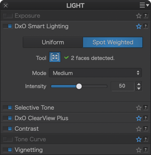
DxO Smart Lighting
About DxO Smart Lighting
Ordinarily, image corrections are applied to the whole photograph: when you modify the brightness or the contrast, you make the whole image brighter, darker, and more or less contrasted.
DxO Smart Lighting’s Uniform mode lets you automatically brighten or darken certain areas in your image without affecting other areas. You can also modify the contrast wherever necessary, such as in the following cases:
- Images with areas that are backlit.
- Images with a contrast range markedly higher than a camera can handle, especially images with very dark areas.
- Images that were accidentally underexposed, generally short on contrast, or lacking a flash fill-in.
As for Spot Weighted processing, it uses face detection and works with Smart Lighting to give priority to correctly exposing faces. This is not precisely a local correction, but rather a way to weight the exposure in favor of faces while preserving the correct exposure of the rest of the image, for a balanced and natural result.
DxO Smart Lighting: Uniform mode
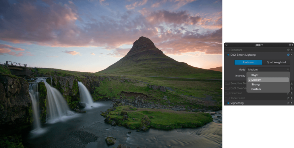
As with the majority of corrections, DxO Smart Lighting’s Uniform mode functions automatically. In this case, the software analyzes the image content and applies the correction in a homogenous way. You have two tools you can use either together or separately to adjust the correction:
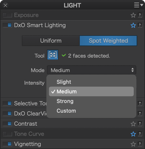
- The first is a drop-down menu that lets you modify the intensity of the correction by choosing among four different levels: Strong, Medium, Slight (default setting), and Custom adjustments.
- The Intensity slider is set at the value assigned to the chosen automatic correction mode: 25 for Slight (default setting), 50 for Medium, and 75 for Strong. You can modify these slider settings, in which case the drop-down menu will display Custom mode.
DxO Smart Lighting: Spot Weighted mode
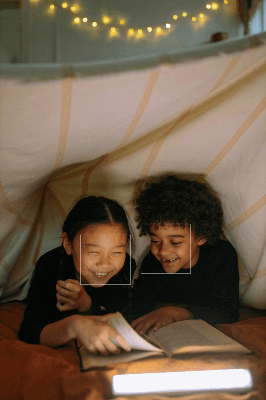
DxO Smart Lighting’s Spot Weighted mode is based on detection of faces in a photo in order to optimize the exposure — without radically modifying the rest of the image. This feature is particularly useful in the following cases:
- Backlit faces.
- Faces that are too bright or too dark against the background, whether dark or bright (e.g., bright on a dark background, bright on a bright background, etc.).
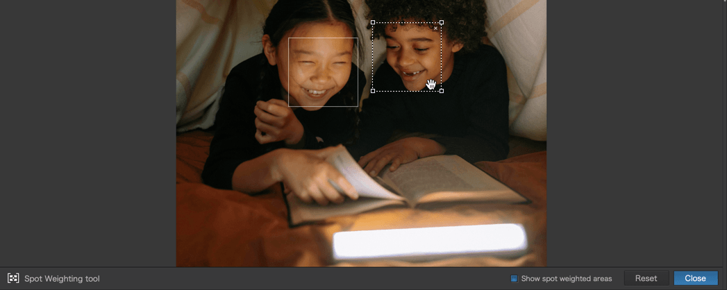
When you click on the Spot Weighted button, DxO Smart Lighting will apply a correction in Slight mode by default, taking into account the faces present in the image. The number of areas detected is indicated in the sub-palette, to the right of the Spot Weighted processing tool icon.
To see the detected areas, click on the tool icon. In the image, each detected face is surrounded by a rectangle. If you move the mouse over one of these rectangles, it will activate (that is, its sides will appear as dotted lines and there will be handles in each corner), thus letting you move it, resize it, or delete it (for this last, click on the cross in the upper right corner of the frame).
You can also use the mouse’s cross pointer to draw a new area. When you do this, the software will perform a new analysis and apply a new correction to the image.
If the system does not detect a face when you turn on Spot Weighted, a No faces detected message will appear in the DxO Smart Lighting subpalette. Generally speaking, non-detection occurs when a face is partially hidden. In these cases, you can manually draw a rectangle, and here, too, the software will perform a new analysis and apply a new correction to the image.
The toolbar located underneath the image lets you activate and deactivate the display of weighted areas (rectangles); to reset the correction; or to close the tool (which you can also do by clicking on the icon in the sub-palette).
You can change the intensity of correction by choosing from among three predefined modes (Slight, Medium, Strong), or by using the Intensity slider to make manual adjustments. In every case, the algorithms take faces into account.
Which settings to use with DxO Smart Lighting
DxO Smart Lighting is probably the most complex of our corrections. It has a global and a local effect on the image – affecting the whole picture and local details – and has a strong influence on contrast and brightness. Such a complex correction can only be mastered with practice. However, you will quickly see for yourself how effective DxO Smart Lighting is even for difficult images.
First, reserve it for photos where the shadows need to be brought back. It has little effect on highlights, unlike Exposure Compensation. Second, you should stick with the three automatic correction modes as much as possible, as they can cope with most situations, and then fine-tune with the Intensity slider afterwards. If you need to do further corrections, use the Selective tone palette or the Tone Curve.
Selective tone
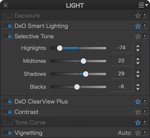
The Selective tone palette is a very intuitive and precise way to control and adjust the brightness of well-defined tonal ranges in an image:
- Highlights: This slider is designed to recover information and details in the brightest parts of the image (e.g., skies with bright clouds, the outside seen through an interior window pane).
- Midtones: This slider acts on the midtones, as represented in the central part of the histogram.
- Shadows: This slider lets you brighten the shadows and dark areas in an image.
- Blacks: This slider lets you set the black point (left end of the histogram) in your image. To the left, the slider progressively changes the dark areas to solid black and, to the right, progressively lifts the black levels and makes them brighter (the left end of the histogram will move to the right, leaving no image data in the blacks).
– The Selective tone sliders can drastically change the contrast of your pictures. Use them in moderation and check your histogram to avoid clipping.
– The Selective Tone slides are also available in the Local Adjustments.
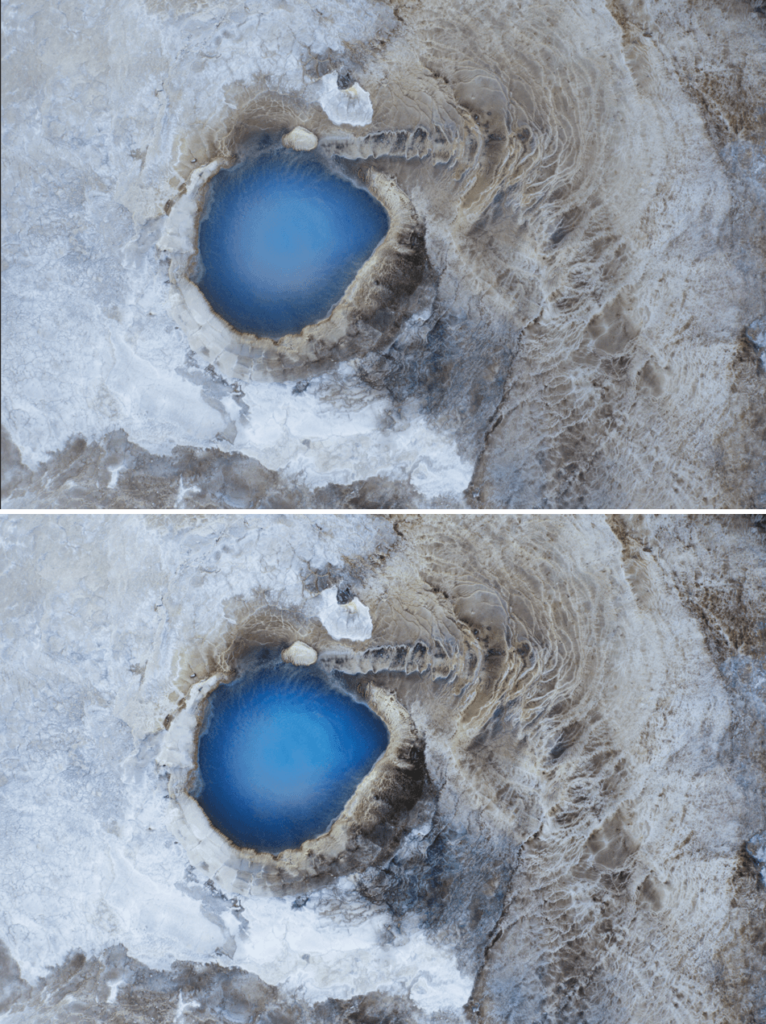
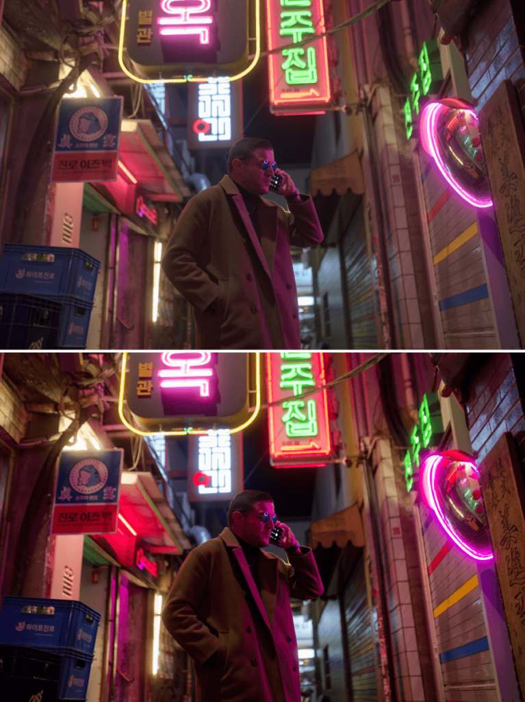
DxO ClearView Plus (ELITE Edition)
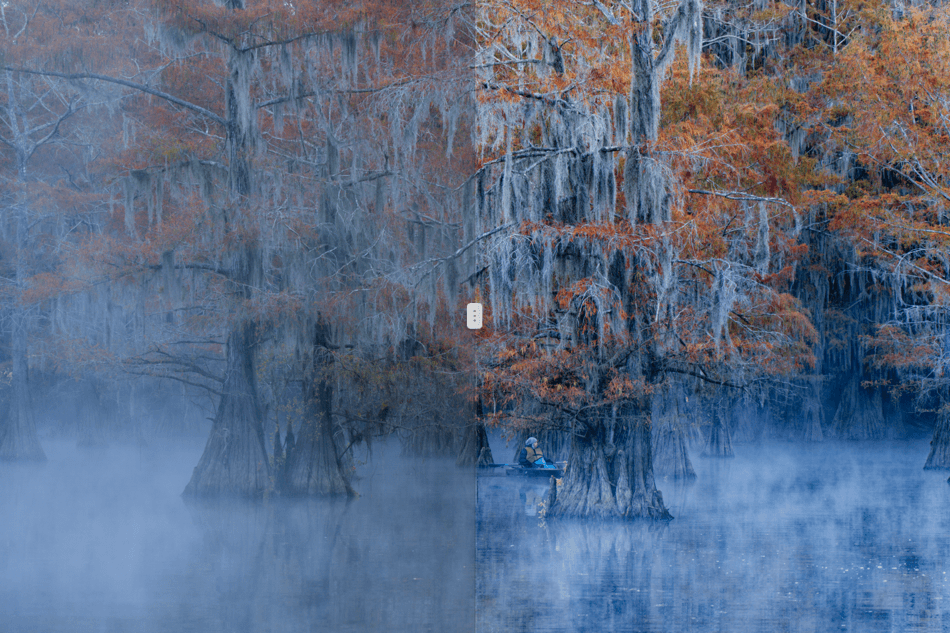
Atmospheric haze is caused by heat, humidity, or pollution, and frequently causes problems in landscape photos by obscuring details and adversely affecting contrast.
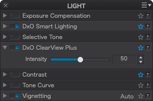
The Intensity slider, set at 50 by default, lets you choose the strength of the correction ranging from 0 to 100.
To return to the default setting (50), double-click on the slider.
You can also use DxO ClearView Plus on images that do not have atmospheric haze, for example to enhance the presence of a sky or landscape.
Contrast
The Contrast sub-palette consists of the Contrast and Microcontrast sliders.
If you have installed DxO FilmPack (ELITE Edition), four other sliders will also be present: Fine contrast and three advanced settings tied to it: Highlights, Midtones, and Shadows.
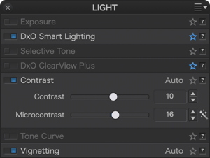
- Contrast: This is the global contrast that acts on the entire image. DxO PhotoLab corrects this by applying a classic S-shape tone curve that contracts the deep shadows and the brightest highlights while stretching the midtones. This correction is implemented using a slider whose most extreme values are –100 and + 100.
The global contrast correction can interfere with the Tone curve settings.
- Microcontrast: also called local contrast, delivers fairly similar results to sharpness correction, but without the inconvenience of generating artifacts. Microcontrast brings out the details and gives the image more “bite.” It is ideal for landscape, architectural, and industrial photos.
You can adjust the Microcontrast in two ways:
- Manually, by moving the slider to the right (stronger), or to the left (weaker).
- Automatically, by clicking on the magic wand to the right of the slider.
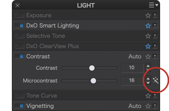
Automatic mode takes into account the presence of faces in order to preserve them, and also takes into account digital noise so as to avoid accentuating it excessively. For JPEG images, automatic Microcontrast is limited to a value of +5.
To reset the automatic correction, click again on the magic wand.
We advise you not to apply a strong Microcontrast correction, especially if you are applying the Sharpness Mask correction from the Detail palette.
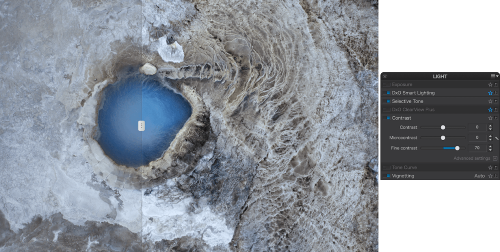
- Fine contrast (DxO FilmPack ELITE Edition installed): The Fine contrast slider brings out or softens medium-sized details, and is gentler in its effects than the Microcontrast, slider, making it appropriate to use with portraits.
- Advanced settings (DxO FilmPack ELITE Edition installed): The Advanced Settings section offers three additional sliders for Fine contrast that act in a selective manner on the following three light ranges:
- Highlights
- Midtones
- Shadows.
Each slider range goes from –100 to +100, with the default value set at 0.
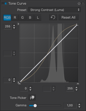
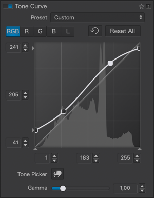
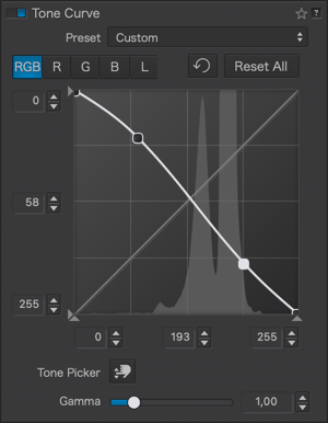
Tone curve
About the Tone Curve
The tone curve is a photo editing tool often considered complex by photographers, sometimes to the point of avoiding its use. However, it is one of the most powerful, flexible, and refined image editing tools available. Don’t be intimidated by the lengthy description here. While the Tone Curve tool requires some learning, once you grasp its principles, the best way to master it is through practice.
The Tone Curve tool not only affects brightness and contrast but also color, via a global RGB channel, three separate channels (R for red, G for green, B for blue), and a luminance channel, also known as luma, which allows you to adjust tones without affecting color. You also have a tone picker that lets you sample a brightness level and mark it on the curve as a point, and make adjustments directly in the image.
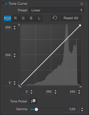
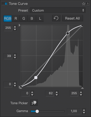
By default, the tone curve is neutral and applies no correction, even when the Tone Curve sub-palette is activated. At this stage, it is represented by a 45° diagonal line, where the input brightness values, represented by the X (horizontal) axis match the output values exactly, represented by the Y (vertical) axis. When you adjust the curve, the output values change, impacting brightness, contrast, and color. Photographers frequently use it to enhance their images with the well-known “S-shaped curve”, which compresses the highlights (represented by the top of the curve, upper right) and shadows (bottom of the curve, lower left), while extending the midtones (center of the curve). The more pronounced the “S”, the stronger the image contrast, meaning the difference between light and dark tones.
Adjusting tones with the curve also affects color by decreasing or increasing saturation depending on your settings, but you can also use it to correct or enhance a color cast with the three RGB channels. For instance, if your image is cooler and leans towards blue, you can adjust the B channel curve from blue to yellow, its complementary color, or vice versa to cool down a warm image. Manipulating the individual R, G, and B channels is also a good way to explore creative renditions.
Finally, the L channel, for luma or luminance, lets you adjust tones while preserving color. For example, if you enhance the tone of a landscape image with gray clouds, they might gradually turn blue, whereas with the L channel, they will remain gray. This is also a way to preserve skin tones in a portrait.
Inverted Curve
The tone curve in DxO PhotoLab also has an inverted mode, allowing you to convert and work on negative images, including scans of analog film.
Description
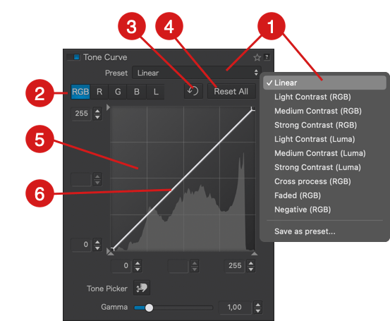
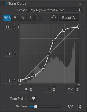
The Tone Curve sub-palette consists of the following elements:
- Presets: When you activate the tone curve, the default preset applied to your image, whether RAW or JPEG/TIFF, is the Linear curve. The dropdown menu allows you to apply curve presets included with DxO PhotoLab and create your own presets (see below).
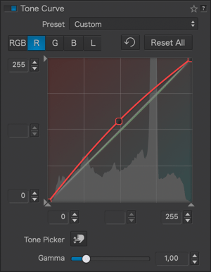
- Channel selection: Click on one of the tabs to select and use the curve in the channel of your choice. Note that you cannot select and activate multiple channels simultaneously, but you can adjust multiple channels, one after the other (e.g., using the global RGB channel and then modifying the red channel).
- RGB: The global channel, where the curve affects all three red, green, and blue channels identically.
- R, G, B: Depending on your selection, the curve affects the red, green, or blue channel.
- L: The curve acts on the luma channel to adjust luminance while preserving color.
- Reset: Click this button to reset the active channel’s curve and associated settings.
- Reset All: Resets all channels and associated settings, returning the curve to the default preset (linear).
- Histogram: the background of the curve displays the histogram of the original image and the corrections that were made before working on the tone curve. When using the tone curve, and as long as you do not make corrections with other tools, its histogram does not change and serves as a reference. To check your curve settings, you need to consult the Histogram palette, which takes all corrections into account (don’t hesitate to enable the clipping indicators and select individual channels to avoid going too far with your adjustments). The appearance and color of the background also change depending on the active channel:
- RGB or L: Gradient gray background, lighter at the top left, darker at the top right, indicating brightness (brightening by curving upward, darkening by curving downward).
- R, G, or B: The background represents the complementary colors, according to the additive color model, and based on the selected channel (R: red/cyan, G: green/magenta, B: blue/yellow). For example, for the green channel, curving upward adds a green cast, and downward, a magenta cast.
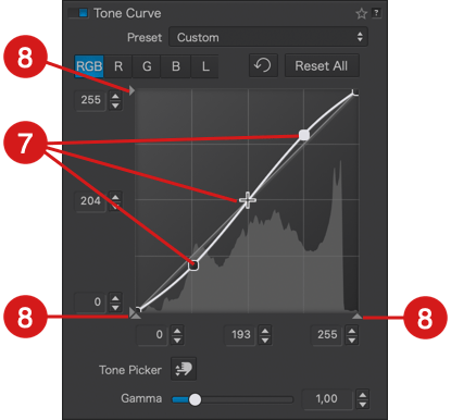
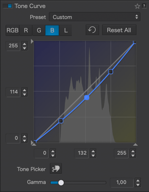
- Curve: By default, the curve is a 45° diagonal line starting from the bottom left corner (absolute black, value: 0*) and ending in the top right corner (absolute white, value: 255*). The curve’s center is marked by the value 128 on each axis. The grid represents input values (horizontal or X-axis) corresponding to the original image tones and output values (vertical or Y-axis) corresponding to the tones after adjustments. To help with interpretation, click on the curve to add a point and drag it with the mouse: if you draw a vertical line from the point to the X-axis below, you’ll get the corresponding value in the original image, and a horizontal line to the Y-axis on the left shows the value after correction. The curve’s color depends on the channel, and if multiple channels are used, you’ll see multiple curves, each in its respective color:
- RGB: white.
- R, G, or B: respective colors, red, green, or blue.
- L: gold.
- Curve Points: When hovering the mouse over the curve, the cursor changes to a cross (+), and clicking sets a point corresponding to a brightness level in the image, with the value shown in indicators on the left (Y -axis) and below (X-axis) the curve (see point 9 below). Be aware that a point on the curve will affect all corresponding brightness levels, regardless of their location in the image:
- You can create as many points as you want.
- To adjust the curve, click on a point and drag it.
- A point becomes white when clicked, indicating it’s active. A black point is inactive.
- You can’t activate multiple points at once.
- To temporarily deactivate all points, click on the background.
- When adjusting the curve between two points, only the corresponding portion of the image is affected. However, the curve accounts for transitions, causing slight variations beyond the points between which you adjust.
- Points on one channel are not visible on other channels (note: all curves are visible on all channels).
- To delete a point, activate it and press the Backspace or Delete key on your keyboard.
- You can also create points using the tone picker (see point 10 below).
- Thresholds: At each end of the X and Y axes, you’ll see small triangles. These handles allow you to modify the values of the white point (0) and the black point (255), also known as thresholds. This lets you adjust the input points and the range of brightness within which the curve will operate:
- On the X-axis, this allows you to adjust the tonal range of an original image whose histogram doesn’t extend sufficiently to the darkest and/or brightest tones.
- On the Y-axis, this allows you to truncate output values, achieving effects like the matte look illustrated thereafter.
- You can check the thresholds in the level indicators (see point 9 below).
- Level Indicators: On each of the X and Y axes, there are three level indicators representing:
- X-axis, from left to right: shadow values, midtones, and highlights.
- Y-axis, from top to bottom: highlight values, midtones, and shadows.
- The indicators also serve as input fields, especially if you have specific values from 0 to 255 to apply. You can also increment them using the up/down arrows on their right.
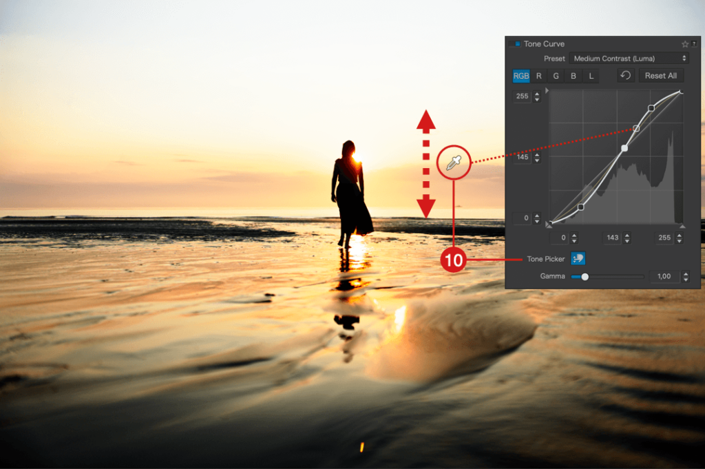
- Tone Picker: Activated by clicking the button, the tone picker offers two functions for convenient interactions with the image:
- You can create points on the curve by clicking in the desired spots in the image.
- You can click on a specific spot in the image and then drag the eyedropper up or down to adjust the tone.
- To deactivate the eyedropper, click the button in the sub-palette again.
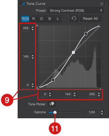
- Gamma: In photography, this value, also known as the contrast factor, determines the contrast of the image capture medium, whether it’s film or electronic sensors. In the Tone Curve tool, it determines the slope of the central section of the curve (midtones), and it’s set to 1.00 by default. You can modify it on a scale from 0.05 to 6.00, either with the slider, by entering a value in the indicator, or using the up/down arrows:
- Values above 1 increase contrast and bring out details in the shadows.
- Values below 1 decrease contrast and bring out details in the highlights.
Let’s do some maths !
* The 0 to 255 levels, 256 levels in total, are a standardized representation used by photo software, based on 8-bit files, or the number of bits per channel for RGB: 2 to the power of 8 (28) equals 256, which is typical for JPEG files that are 8-bit. For information, 16-bit files (216), like TIFF or RAW files, have 65,536 levels per RGB channel, but a representation with 256 levels is simpler to present and use.
Presets
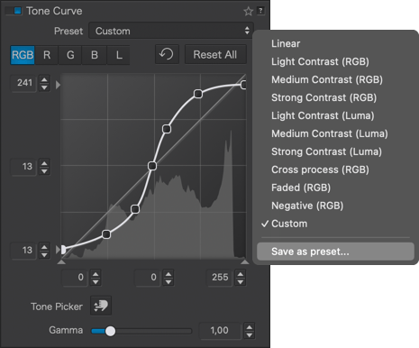
The tone curve comes with several presets. For learning, feel free to try them and carefully observe all the associated settings in the sub-palette.
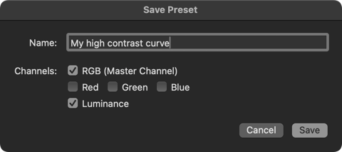
You can also create your own tone curve presets:
- Adjust the tone curve.
- In the Presets list, select “Save Preset…”.
- A dialog box appears allowing you to:
- Enter the name of your custom preset.
- Exclude or include the different RGB and Luminance channels.
- Click “Save”.
- Your preset appears in the list.
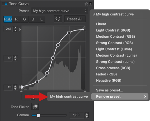
To delete a custom preset*:
- Go to the list, select “Remove Preset”.
- Choose the preset from the submenu.
- A dialog box asks you to confirm the deletion.
*You can’t delete the tone curve presets provided by DxO PhotoLab.
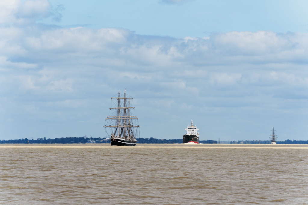
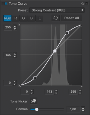
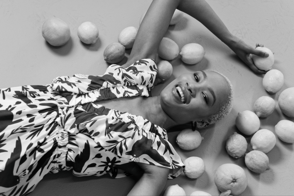
Here are some examples of using the tone curve with associated curve settings:
Original
Increasing contrast
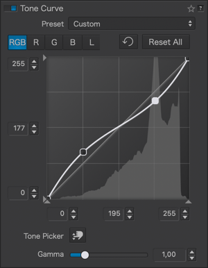
Decreasing contrast
Original
RGB contrast enhancement
Luma contrast enhancement
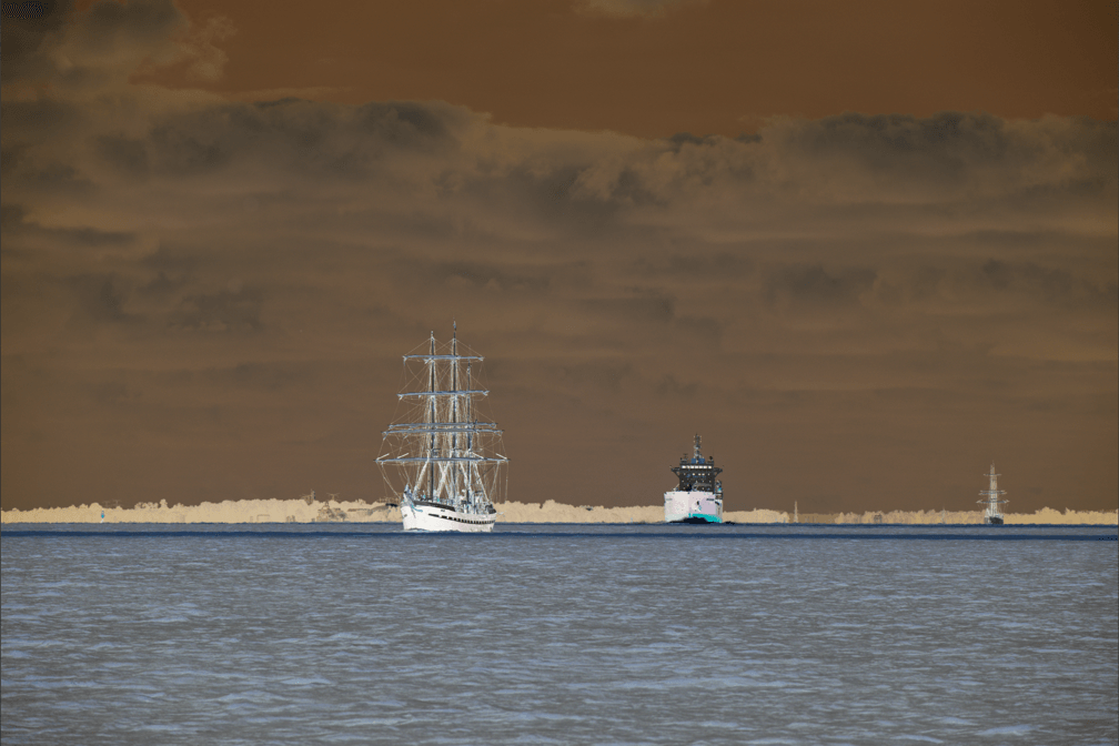
Correcting a color cast (here with the blue channel)
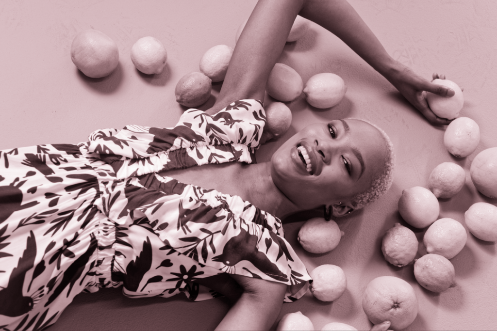
Toning a black & white picture with color channels
Matte effect
Inverted curve negative/positive
Vignetting
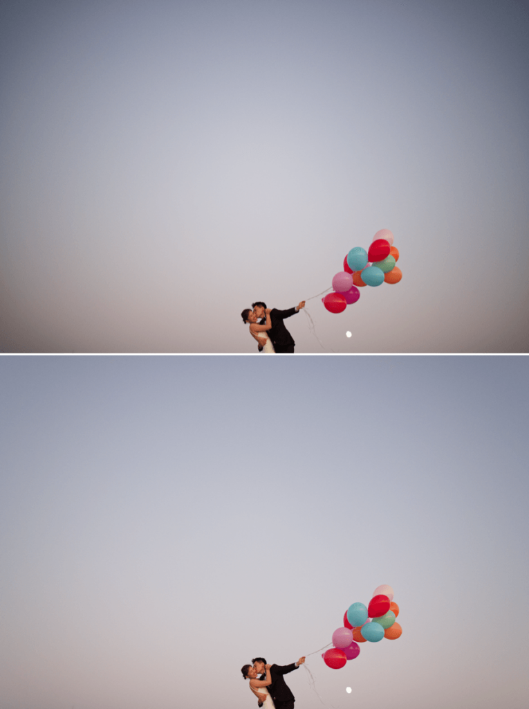
Vignetting is an optical aberration that results in corners and edges that are darker than the center of an image. The vignetting correction works differently and uses different commands depending on whether or not the relevant DxO Module is available.
DxO Module available
When a DxO Module is available, the Correction drop-down menu will display Auto with DxO Module, and the correction will be automatic. You also have the option to refine the correction by hand, or switch to a completely manual mode, as if the DxO Modules were not available (see the next paragraph).
The vignetting correction actually takes place in two steps, both of which can be fine-tuned:
- First, from the lens data, focal length, and aperture setting, the DxO Module calculates the necessary correction for every pixel in the image. The Intensity slider allows you to decide how much vignetting should be removed (within a range of 0 to 100%).
- Second, a filter is applied to avoid clipping in bright areas and increased noise in dark areas. You can use the Preservation slider to set the intensity of this filter (from 0 to 100%), as follows:
- If set to 0%, the vignetting correction will be applied without any restrictions.
- If set to 80%, for example, the largest highlights and shadows will remain uncorrected.
When adjusting these two combined settings, we suggest sticking to the default 100% for the first Intensity slider, since the Middle slider is usually more effective in preventing undesirable vignetting correction side effects. Only vignetting due to the lens or sensor is corrected. Mechanical vignetting caused by a lens shade, for example, cannot be corrected. In the case of mechanical vignetting, you may want to use the Crop tool to remove the unwanted parts of your picture.
As with many other DxO PhotoLab corrections, the magic wand allows you to revert to the default settings.
No DxO Module available
If the DxO Module is not available, manual mode will be displayed. The Intensity slider will visually correct the darkening of the image at the edges and, in the advanced settings, the Middle amplification slider lets you determine the extent of the effect from the center of the image.
The Color palette
Working Color Space
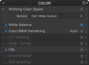
DxO PhotoLab (from version 6) uses an extended color workspace: DxO Wide Gamut, in addition to the Classic profile (Legacy), which matches the Adobe RGB 1998 profile, kept to prevent users from applying unwanted changes to images that they have already processed. The Colorimetric Space Subpalette lets you to manage images according to their color profile and convert them:
- All images processed in versions prior to DxO PhotoLab 6 will use the Classic colorspace, but you can convert them to the DxO Wide Gamut space.
- All new images opened in DxO PhotoLab 6 use the DxO Wide Gamut color space, for even richer colors.
Converting images processed in Adobe RGB to the DxO Wide Gamut profile may change some colors and so, depending on how the picture looks, you may need to redo some corrections.
Indeed, soft proofing is available for the DxO Wide Gamut space, as well as the Legacy colorspace.
Important
Since version 6 (October 2022), DxO PhotoLab is no longer constrained by the color space of the input image, as each one is converted to use the expansive DxO Wide Gamut color space. For most screens with restrained color spaces, out-of-range color warnings may appear in the Soft Proofing tool when correcting images. However, getting rid of these warnings should not be your aim as they do not concern the quality obtained in exported files or prints.
Since DxO PhotoLab 6.3 (February 2023), the DxO Wide Gamut color space applies to both RAW and RGB files (JPEG, TIFF, linear DNG).
White Balance
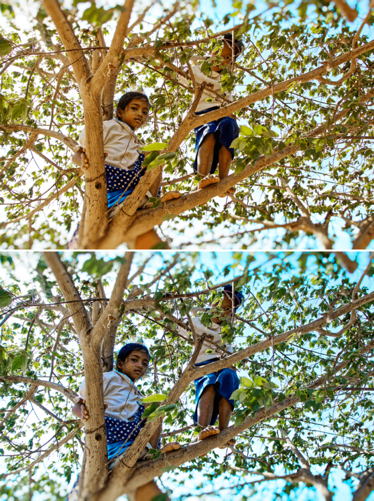
Regardless of its origin (artificial or natural), light usually appears white to our eyes. It is, however, nothing of the sort. Even daylight can contain strong blue dominants, particularly in shadows or when the sky is overcast. At the other end of the spectrum, incandescent bulbs have a yellow cast, while fluorescent lights produce complex green casts.
Adjusting white balance serves to correct these undesirable light dominants.
The settings available depend on the file type:
- For a RAW file, the white balance has yet to be established, and you can use any of the available tools in the palette.
- For a TIFF or JPEG file, the white balance has already been performed by in-camera processing (JPEGs), or by another software or image editor (TIFFs). Consequently, you are limited to using just the Pick Color eyedropper and the Temperature slider to adjust the White Balance correction.
When you select a RAW file or a RGB file (JPEG or TIFF) in the Image Browser, the White Balance palette automatically adapts accordingly.
Using presets (RAW files)
The drop-down Setting menu contains a certain number of settings that cover most known light sources, ranging from daylight, cloudy, or shade to tungsten, different types of fluorescent, or industrial (sodium, mercury) lights.
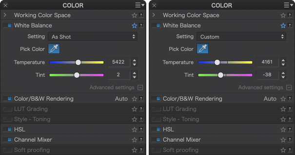
The default choice is Original, which corresponds to the white balance of the camera used to shoot the image. Manual or Custom mode is automatically selected as soon as you use the Color temperature or Tint sliders (see the corresponding paragraphs further below).
The presets are:
- Daylight (Temperature 5,200 K, Tint 0) corresponds to light in the middle of a clear, cloudless day.
- Cloudy (Temperature 6,000 K, Tint 0) compensates for the slight coolness and blue dominant of a cloudy sky.
- Tungsten (Temperature 2.850 K, Tint 0) compensates for the strong orange dominant of light found in certain industrial sites, community halls, etc.
- Fluorescent (Temperature 4.000 K, Tint 0) compensates for the warm dominant of neon tubes.
- Flash (Temperature 6.100 K, Tint 0) compensates for the slightly blue light of an electronic flash.
- Aquatic (Temperature 15.000 K, Tint 150) compensates for the strong blue-green dominant in underwater photos.
- Shadow (Temperature 7.000 K, Tint 0) compensates for the marked cold dominant in photos taken in the shade.
- Manual: Activated when using the eyedropper.
Extending white balance to 50,000 allows for very specific corrections, such as those for the Aquatic preset that efficiently compensate for the strong blue-green dominant in underwater images.
The original white balance is the only camera setting that DxO PhotoLab takes into account.
Using the eyedropper (RAW and RGB files)
To use the eyedropper, you will first need to find an area or element in your image that is as close as possible to a neutral gray color, preferably a relatively light gray. Next, click on the area to establish the white balance. You can do this as many times as you want until you achieve the result you are looking for.
If the neutral area repeats in the image is small, zoom in to perform a more accurate pick.
Underneath the Viewer (Mac), or above it (PC), you will find a Radius slider that will allow you to change the size of the sampling area (indicated by a circle that accompanies the eyedropper). You can adjust the radius from 1 to 50 pixels.
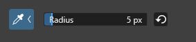

For images taken at high ISO speeds, we recommend increasing the Radius slider value to 10, to reduce pointing errors due to possible noisy patches.
After you finish using the white balance eyedropper, click on Close in the bottom right of the toolbar directly underneath the image.
Fine-tuning the white balance of a RAW file
However you choose to initially correct your images for white balance — via pre-established settings or the eyedropper, you can fine-tune the corrections using the Color temperature and Tint sliders. The Color temperature slider has a range of 2,000 °K to 50,000 °K, and can often be combined with the Tint slider to remove residual colorcasts.
In all cases, choosing As shot in the drop-down menu lets you safely revert to the settings provided by the image EXIF data.
Fine-tuning white balance for a RGB file (TIFF or JPEG)
When you select a JPEG or TIFF file in the Image Browser to set the white balance, the RAW white balance palette changes automatically to the RGB white balance palette, in which a simplified Color temperature slider is available in addition to the color picker. Strictly speaking, it is not possible nor recommended to set the white balance for a JPEG or TIFF file, since the white balance has already been established by in- camera processing. Therefore, any modification in one tonal range will produce imbalances in other tonal ranges: if we correct the midtone greys, then highlight greys or low-key greys will inevitably suffer a slight colored hue. For this reason, any white balance adjustments on images like his should be very slight. You can use either the color picker (eyedropper — see above) or a dedicated slider, both available in the advanced settings (Mac), to move from cooler (blue) tones to warmer (yellow) tones and vice-versa.
To reset slider adjustments, double-click on the slider. For both RAW or RGB files, it is not always necessary to look for perfect white balance. Keep in mind the atmosphere of the scene you have photographed, and try to adjust the settings to maintain that atmosphere.
Color/B&W Rendering
Color/B&W switch
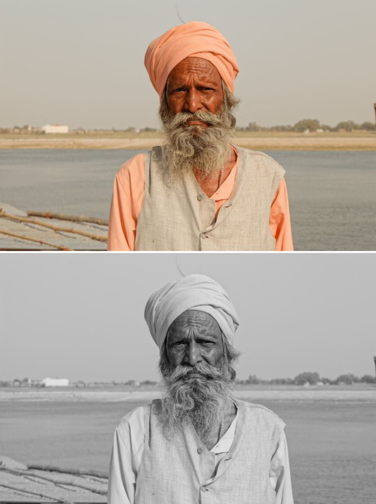
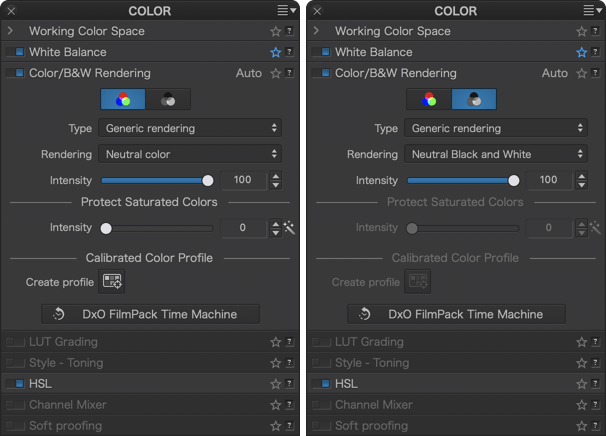
The Color/B&W Rendering palette allows you to easily switch between workflows using the Color and B&W buttons. By clicking on either of these buttons, the content of the palette automatically adapts to the selected mode.
In B&W mode, the following tools are disabled :
- Protect Saturated Colors
- Calibrated Color Profile
- HSL subpalette: Vibrancy
Every camera, every processing software, and for traditional photography, every film, has a particular color rendering (and some renderings have contributed positively to their manufacturers’ reputations). The purpose of the Color Rendering palette is to simulate the rendering of a camera or film. Beyond aesthetics, this correction has a practical application for photographers who work with multiple cameras, enabling them to unify the appearance of their images regardless of the camera used. And professionals might also want to deliver to their customers a neutral set of images that bears no noticeable signature of any particular camera.
By default, DxO PhotoLab applies the following renderings to RAW files:
- Color:
- Type menu: Generic rendering
- Rendering menu: DxO – Natural
- B&W:
- Type menu: Generic rendering
- Rendering menu: Neutral Black and White
RAW images
Because RAW images still contain all the luminance information and have never been converted into any color space, they are particularly suitable for the Color rendering correction. This means that many creative opportunities are open to you, as you can see from the contents of the two drop-down menus, Type and Rendering, which also depend on the Color or B&W modes:
- Generic renderings (Color mode selected): When this option is selected, you will find, In the Rendering dropdown menu, the following renderings :
- DxO Camera Profile (for the camera used in the selected RAW file).
- DxO Vibrant, Vivid and Natural renderings.
- DxO Portrait 1, Portrait 2 and Portrait 3 renderings.
- Neutral Color.
- Generic renderings (B&W mode selected):
- Neutral Black & White
- DxO – B&W Faded, Balanced and Strong
DxO PhotoLab does not take into account the photo styles provided by some camera makers. However, it will try to match the standard original rendering as closely as possible. Note that DxO PhotoLab lets you apply Fuji renderings (see below).
- Camera body (ELITE edition): When selected, this option reveals (in the second drop-down menu) a long list of cameras of different makes and models which DxO Labs has tested and measured, and whose color renderings you can use.
- Color Positive Film (Color mode selected): Without the DxO FilmPack plugin, DxO PhotoLab offers by default one single choice, Color Positive Film, and a small selection of Fuji and Kodak positive films.
- Black and White Film (B&W mode selected): Without the DxO FilmPack plugin, DxO PhotoLab offers by default one single choice, Black and White Film, and a small selection of Fuji, Ilford, and Kodak black and white films.
If DxO FilmPack is installed and activated, the Type and Rendering drop-down menus offer more films in the following categories : Color Positive Film, Color Negative Film, Color Processed Film, Digital Film, Cinematic Film and Black & White Film. For more information, please refer to the DxO FilmPack user guide.
- DCP profile (ELITE edition): See the Calibrated Color Profile section, afterwards, for more information about DCP profiles and how to import and/or create them.
- Intensity Slider: The Intensity slider enables gradual changes to the rendering of the original image in another color render. 0 matches the original image, 100 is the default setting. If the color profile is Classic (old), values above 100 will allow for extreme corrections. If the color profile is DxO Wide Gamut, the maximum value is also the default 100.
- Protect saturated colors (RAW images only): The Protect saturated colors correction prevents some specific saturated colors from being clipped, which may lead to unnatural colors and loss of texture when a particular color channel is close to the minimum or to the maximum luminance intensity (0 or 255). This process is performed automatically; you can fine-tune or modify the result with the Intensity slider. Clicking on the magic wand restores the image to the original automatic setting.
Fuji and Nikon images
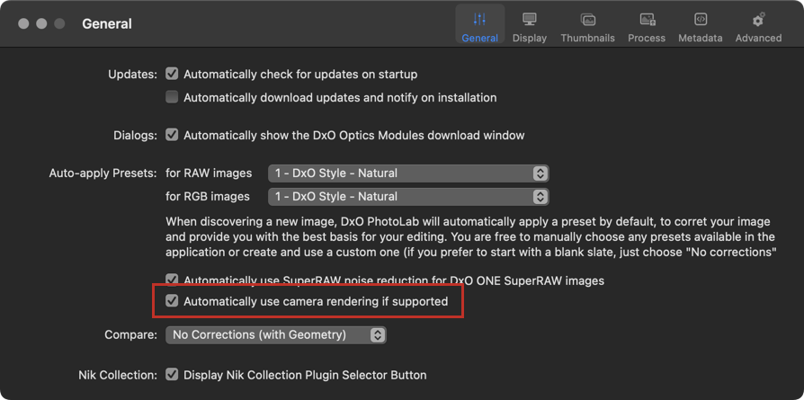
If you are using a Fuji or a Nikon camera, you have the option to automatically apply the camera’s rendering. To do this, you will need to activate the option Automatically use camera rendering if supported in the Preferences > General tab of DxO PhotoLab. There are two possible scenarios, depending on whether DxO FilmPack is installed or not:
- DxO FilmPack not installed: the rendering will be the generic rendering of the camera, and DxO Photolab will apply this rendering if the camera is set to Fuji film rendering.
- DxO FilmPack installed: in addition to the generic renderings, you will have the choice of all Fuji and Nikon renderings to apply as you wish. Note that in this scenario, you will also be able to apply those renderings to any brand and model of camera supported by DxO PhotoLab (renderings are available either in the Color > Color Rendering > Rendering palette or in the Presets, DxO FilmPack Designer – Color and DxO FilmPack Designer – Black & White sections).
The following renderings are exclusively compatible with RAW images captured using a Fujifilm camera:
- Fuji PROVIA/STANDARD
- Fuji Velvia/VIVID
- Fuji ASTIA/SOFT
- Fuji CLASSIC CHROME
- Fuji CLASSIC CHROME +
- Fuji PRO Neg. Hi
- Fuji PRO Neg. Std
- Fuji CLASSIC Neg.
- Fuji ETERNA/CINEMA
- Fuji ETERNA BLEACH BYPASS
- Fuji SEPIA
- Fuji Nostalgic Neg.
TIFF or JPEG images
As with several other corrections, Color rendering is inherently limited when applied to TIFF or JPEG images: the images have already been processed to some degree, and thus there is no access to the original file data. So for these formats, only certain film emulations are available.
You can access film options by combining certain choices found in the two drop-down menus, Category and Rendering (see below). The Intensity slider allows progressive changing of the original image into the selected emulation. The default setting is 100, with 0 for the original image, and all values above 100 “hyper-correcting” the image.
Color rendering (DxO FilmPack enabled)
Starting with version 6.0, if FilmPack is enabled, the DxO FilmPack Time Machine button appears in the Color Rendering sub-palette. Clicking on it will open the Time Machine floating window that lets you browse through an illustrated history of photography, from the 19th century to the year 2020. You can also apply directly the presets proposed by Time Machine (see the section on DxO FilmPack and Time Machine for more details).
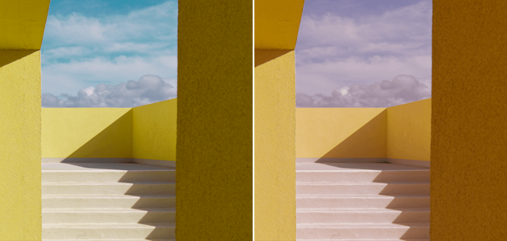
Calibrated Color Profile (ELITE edition)
DxO PhotoLab lets you use DCP input profiles to obtain optimal image rendering and colors, depending on the illuminant used to light the scene, and/or to apply a particular rendering, or even to homogenize the image colors produced by different camera models.
What is a DCP profile?
Your camera’s sensor converts the photons that reach the photosites (the sensitive elements that capture light) into electrical signals. These electrical signals are then converted into data stored in a RAW file which, in turn, need to be processed using software such as DxO PhotoLab to produce a usable image. To restore color throughout this process, the program applies an input profile, and therefore its own rendering.
However, you can change this rendering using another input profile.
DxO PhotoLab supports DCP profiles, a technology developed by Adobe. DCP (DNG Color Profiles) are based on DNG (Digital NeGative), a free and open RAW format that Adobe has provided to the image, photo and film industry, and which has been universally adopted by mobile devices running iOS and Android.
DCPs have a number of advantages over ICC profiles, in particular their flexibility. Indeed, DCPs make it possible to incorporate two types of illuminants — for example, daylight and incandescent lighting — to obtain the right colors and white balance in all circumstances. Profiles also affect image contrast: for example, you can use profiles with a more or less soft rendering, or linear-type profiles, to produce a flat rendered image, thus giving you a neutral working base on which to create your own rendering.
ICC profile support has been dropped since DxO PhotoLab 7 (Sept. 2023).
DxO or Adobe DCP curve ?
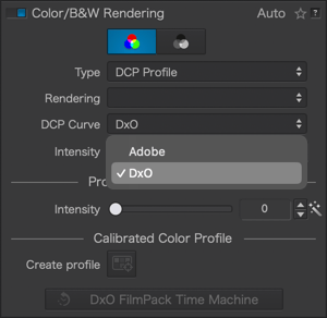
The DCP curve menu appears only when you select DCP Profile in the Type menu, and lets you select two different renderings:
- DxO: this is your choice when you do your image editing fully in DxO PhotoLab. It produces more crispy results and lets you benefit of the full DxO Wide Gamut color space.
- Adobe: this choice will help you to keep rendering consistency if you edit your photos in Lightroom or Camera Raw (check the Workflow with Adobe Lightroom Classic page for a full desciption of the DxO PhotoLab/Lightroom wokflow).
How to create a custom calibrated color profile
DxO PhotoLab lets you create DCP input profiles. If you don’t want to produce your own profiles, service providers are also available to create input profiles for your particular camera.
To create a custom DCP input profile, you need to use a color chart. This will allow you to get accurate colors according to the light source, and apply the saved profile to batches of images taken with the same light source.
- The application of a calibrated profile must be done upstream of the workflow in the Customize tab, and more particularly if you plan to correct the colors.
- The Calibrated Color Profile Tool is only available in the DxO Wide Gamut working color space.
To create a custom profile, you must have one of the following charts:
- Calibrite ColorChecker Classic
- Calibrite ColorChecker Passport Photo 2
- Datacolor Spyder Checkr 24
- Datacolor Spyder Checkr
- Datacolor Spyder Checkr Photo 24
- Datacolor Spyder Checkr Photo
Photographing the color chart
The Calibrated Color Profile creation tool can only be used with RAW files. This is because with a JPEG file, the white balance and color corrections will be limited, while RAW files give you all the latitude for corrections. If you select a JPEG file, the tool will remain inactive.
To photograph your chart, make sure it is well exposed to the light source, frame it so that it fills a good part of the image, especially if you are using a small chart, and that it is facing the lens.
After you have photographed the chart, or the chart with its subject, remove it and then continue your shooting session. If you change the light source or change the subject, take a new shot with the chart.
Creating a Calibrated Color Profile
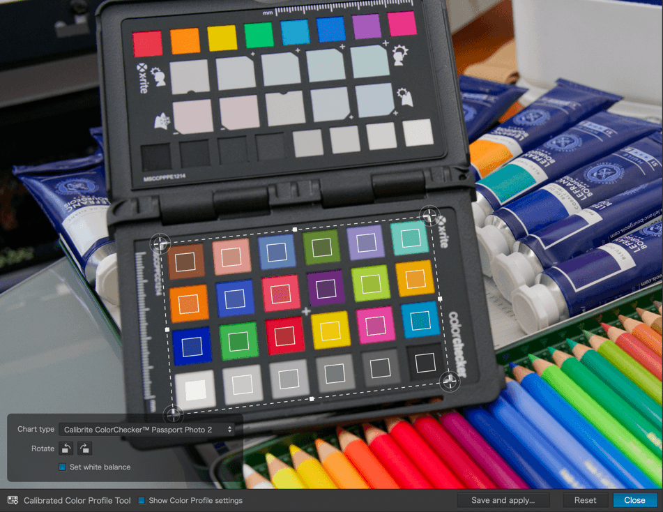
After opening and selecting the image with the chart in DxO PhotoLab, and before making any color corrections (by default, the software adjusts the tones and basic rendering, and the camera’s white balance is preserved), activate the Calibrated Color Profile creation tool in the Colors palette, sub-palette Color Rendering / B&W, then:
- Place the mouse in the image, the pointer turns into a tracing tool.
- Trace the selection rectangle to include all the color patches of the chart, and make sure the patches of the tool are positioned and centered on those of the chart.
- If the color patches of the tool are inverted compared to those of the chart, the settings palette allows you to rotate by increments of 90°. If the chart is not perfectly facing, you can modify the shape of the selection rectangle, by grabbing the corner or the side handles.
- In the settings palette, in the lower left corner of the image, select the type of chart (if you do not see the palette, click on Show color profile settings in the lower toolbar).
- The Adjust White Balance option allows you to neutralize, before saving the profile, the possible light source color cast. This does not change the setting displayed in the White Balance sub-palette, and allows you to adjust it to your liking after applying the calibrated color profile to your images.
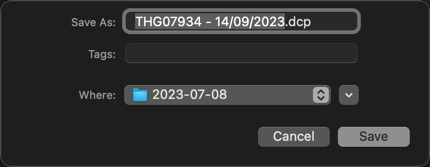
- In the lower toolbar, click on Save and Apply: a dialog box allows you to customize the profile name and choose the destination folder (by default, the profile is named after the image + the date of profile creation + the .dcp extension, and the destination folder is that of the image).
Applying a Calibrated Color Profile
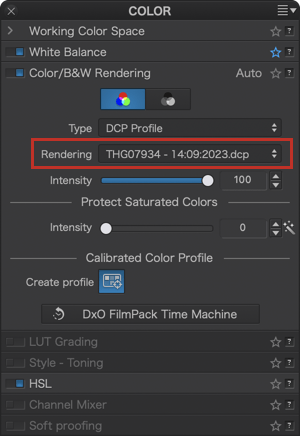
To apply a custom calibrated color profile to an image or a previously selected batch of images:
- Go to the Colors > Color Rendering / B&W palette and, in Type, select DCP Profile. The last used profile appears in the Rendering menu.
- In the Rendering menu, you can choose another profile.
- The Intensity slider, set to 100 by default, allows you to attenuate the rendering obtained with the selected profile.
If, for some reason, you switch to B&W mode and then back to Color mode, the Type and Rendering drop-down menus are reset to Generic rendering and Neutral color. You will therefore need to reselect your calibrated profile.
Importing and applying a Calibrated Color Profile
To import and apply a DCP input profile into DxO PhotoLab:
- Open the Color/B&W Rendering sub-palette, and from the Type menu, select DCP Profile.
- In the Rendering drop-down menu just below, choose Import DCP profile.
- In the system dialog box, locate and select the profile to import, after you click on Open.
- DxO PhotoLab immediately applies the input profile to your image; you can use the slider (set to 100 by default) to adjust the intensity of its effect.
When should you apply a DCP profile? Ideally, you should apply it at the beginning of the workflow, before performing any image corrections:
- As soon as the image is opened in DxO PhotoLab, after DxO PhotoLab has applied the default preset. This solution, which corresponds to the default operation of DxO PhotoLab, will suit the majority of photographers.
- When you are applying a custom preset that includes a DCP profile. This method is intended for photographers who want to keep control of the entire image processing workflow.
LUT Grading (ELITE edition)
Overview
LUT (Look-Up Table) files are tables that modify input values into different output values, especially in terms of colors and their respective RGB values. In DxO PhotoLab, to make things easier, those tables are referred as “LUT files”.
In the case of a digital image, LUT files allow you to practice color grading and give a creative rendering to your images, without modifying or altering the default settings in the Customize tab (unlike the presets of DxO PhotoLab and DxO FilmPack).
The goal, here, by reproducing a palette of colors, is to give a particular look to your image, often inspired by movies or TV series, but also by magazines, landscapes, seasons, etc.
Finally, unlike DCP calibrated profiles, you can apply a LUT file to both Raw and RGB files (JPEG, TIFF).
DxO PhotoLab comes with 3 different sets of LUT files:
- Standard: 17 legacy LUT files.
- Premium: a series of 15 professionnal, fine art grade LUT files developped by Dennis Aydogan, professionnal photographer.
- Custom: this is where you will find your own LUT files, which allows you to import and apply LUT files (in .cube format) available on the Internet, or developed by yourself if you have the necessary tools and knowledge.
Apply a LUT file
The application of a LUT file must be done upstream of the workflow in the Customize tab.
To apply a LUT file to an image or a previously selected batch of images:
- Go to the Color palette, sub-palette LUT calibration.
- Select the desired rendering in one of the LUT file lists.
- If you are using an imported LUT file, and therefore not one of the LUT files from DxO PhotoLab, the LUT Color Space menu allows you to assign a working color space.
- The Intensity slider, set to 100 by default, allows you to attenuate the rendering obtained with the selected LUT file.
Import a LUT file
You can easily add LUT files, after downloading them from the Internet and decompressing them:
- In the Color palette, sub-palette LUT calibration, open the LUT file list and select Import (.cube)…
- A system dialog box allows you to locate and select a LUT file (on PC, you can select multiple files).
- Click OK, the LUT file appears in the list and is applied immediately.
DxO PhotoLab does not move LUT files during import. Provide a dedicated storage folder, such as the Images folder in your system.
Delete a LUT file
Go to the LUT file list, and select Delete. All LUT files, except those from DxO PhotoLab, are deleted.
Style – Toning (DxO FilmPack not activated)
The Style-toning palette offers by default a Sepia preset.
You can adjust the effect with the Intensity slider. The default value is 100, and 0 corresponds to the original image.
The contents of the Style – Toning palette depends on whether DxO FilmPack has been activated or not. For more information, see the section on DxO FilmPack palette.
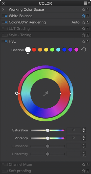
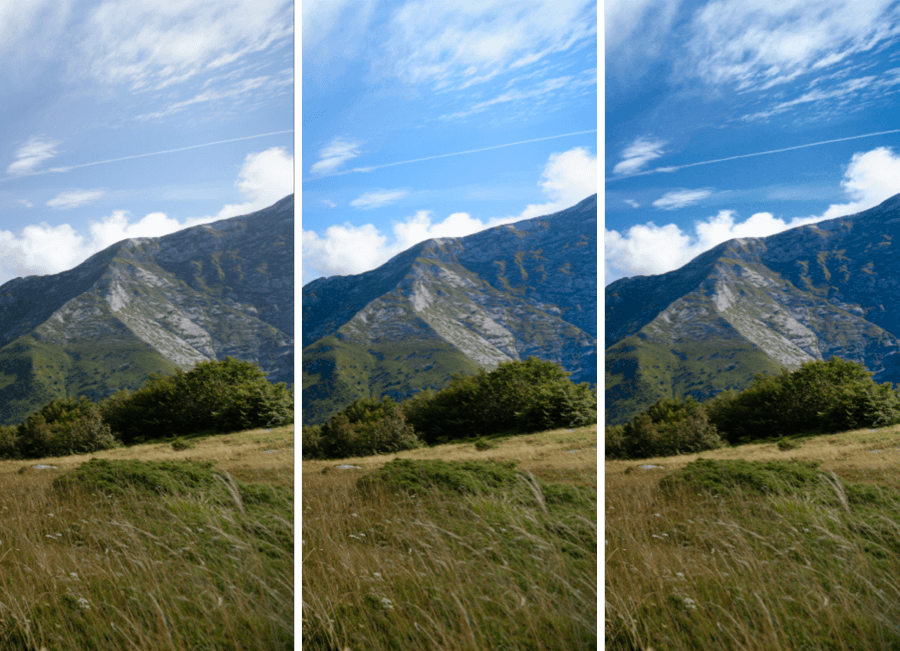
HSL
The Hue/Saturation/Luminance (HSL) palette allows you to selectively and precisely correct colors using a color wheel, 8 color channels, and a global channel, as well as 3 sliders that affect saturation, luminance, and uniformity. This tool also allows you to:
- Reinforce or attenuate colors;
- Modify or even replace colors;
- Standardize (or not) the variations of the hue in within a color.
Color channels
At the top of the sub-palette, the colored dots show the selectable color channels (from left to right):
- Global channel (white dot)
- Red channel
- Orange channel
- Yellow channel
- Green channel
- Cyan channel
- Blue channel
- Violet channel
- Magenta channel
The selected channel is indicated by a white outline around its dot. As soon as you make a hue, saturation, luminance, and/or uniformity adjustment, a white dot appears under the active channel indicator.
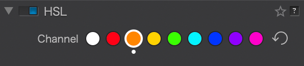
After applying a correction to a channel, you can temporarily disable it by clicking and holding the mouse button in the active channel dot. This allows you to quickly compare the image before and after the correction.
To the right of the channels, the curved arrow resets all the adjustments made in the palette—both to the settings of the color wheel and to those of the sliders. However, the channel you previously selected remains active, as indicated by a white outline.
DxO ColorWheel
The DxO ColorWheel replaces the HSL tool hue slider in versions prior to DxO PhotoLab 3. Equipped with both broader and finer adjustment options, it consists of the following elements:
- An outer wheel, which allows you to change the colors of the image (the “target color”);
- An inner wheel, which represents the source color range when you select a color channel.
- A color sampler.
As the inner wheel represents the source color (the one you want to change) and the outer wheel represents the target color, you should read and interpret the DxO ColorWheel from the inside to the outside.
The behavior of the DxO ColorWheel thus depends on what you select in the global channel or in one of the color channels.
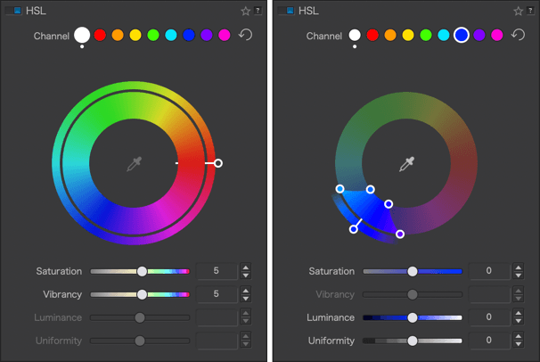
When the global channel (white dot) is selected, only the Saturation and Vibrancy sliders are active.
If the global channel is selected
Using the handle, you can rotate the outer wheel of the DxO ColorWheel 360°, and in this case, each inner color range (source color) will take on the hue it aligns with in the outer wheel (target color).
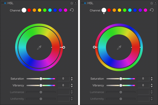
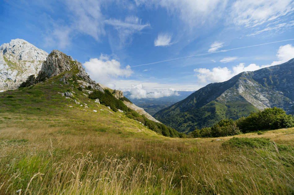
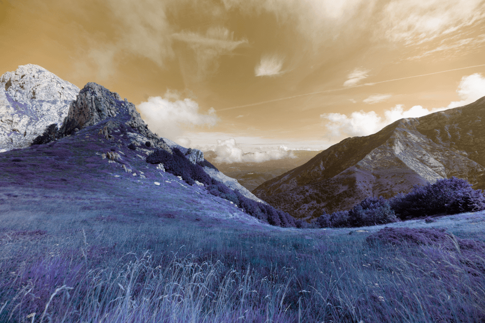
Let’s take the example of a photo with a blue sky and fairly yellow grass:
If the global channel is active (white dot) and no adjustments have been made, the two wheels will be aligned (slider to the right): the blues next to the blues, the reds next to the reds, the greens next to the greens, as well as the complementary colors (yellow, cyan, magenta). The sky and grass maintain their original colors.
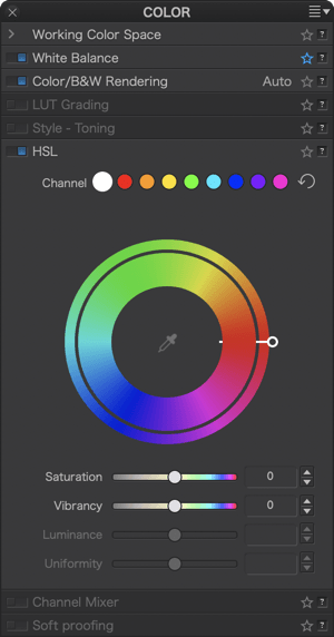
Grab the handle and then rotate the outer wheel so that the handle is at the bottom: the blue range of the inner wheel (source color) ends up aligned with the red/magenta range of the outer wheel (target color) and therefore the sky turns a red/magenta tint. The yellow/orange range of the inner wheel (source color) aligns with the green range of the outer wheel (target color) and thus the yellow grass turns a bluish green.
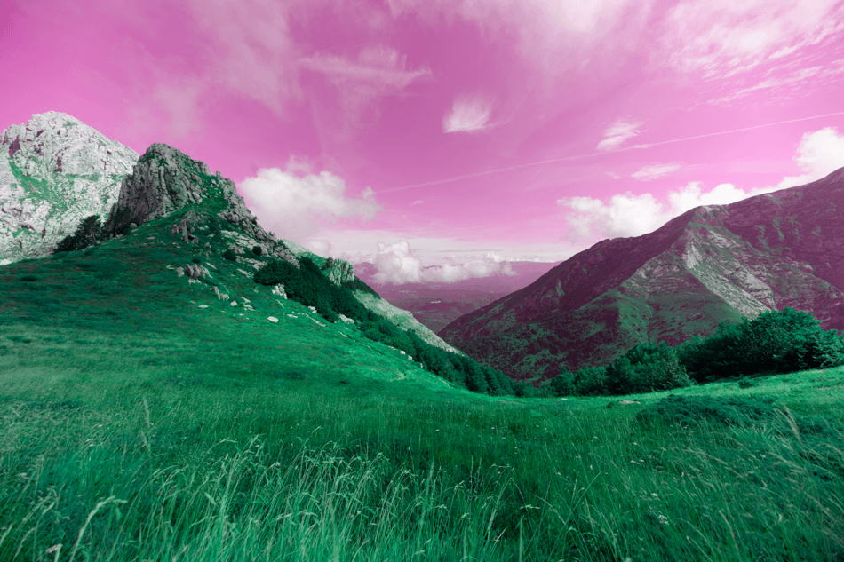
Continue until the handle is positioned to the left of the wheel: the internal blue zone (source color) is next to the orange zone (target color) so the sky turns an orange hue, the yellow zone of the internal wheel is aligned with the blue zone of the external wheel; then the grass turns blue and so on as you return to the default position (slider on the right, in line with the internal marker and both wheels aligned).
If a color channel is selected
Let’s use the same photo as before:

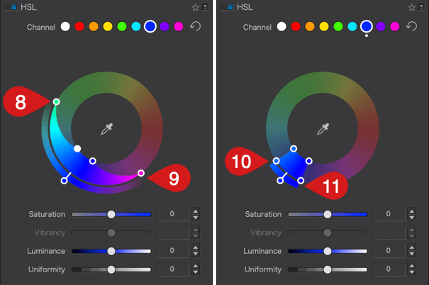
Click on the blue dot to activate the blue channel.
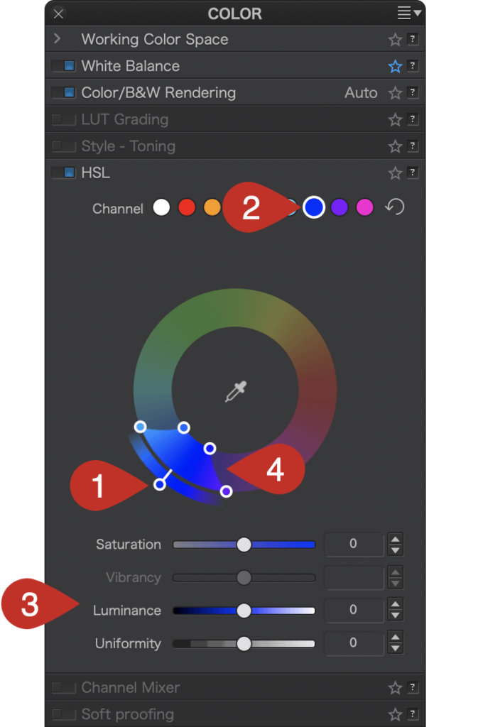
- The color adjustment [1] is limited to blue hues, making them the target color— that is, the color that you want to change; and for the time being, the handle remains on the blue.
- The channel dot is blue [2].
- The Saturation and Luminance sliders are blue [3].
- The color range to be changed is also limited to the blue range [4], with 4 sliders at each corner. You can alter the transition to adjacent colors by using the handles: the two inner handles represent the effective limits of the source color range (blue in our example); the outer handles represent the selected color range.
- By moving the inner handles away from each other [5 & 6] or by moving them closer [7], you can extend or reduce the range of the blue color.
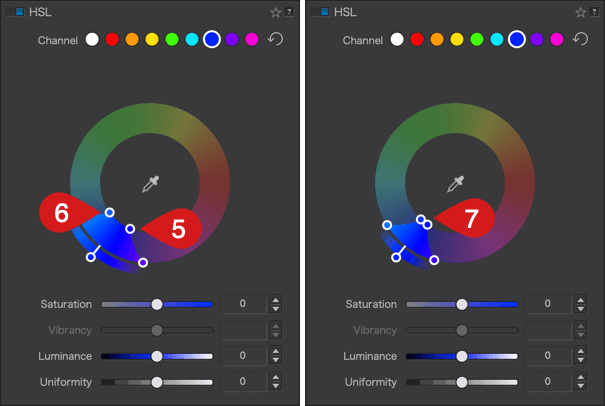
- The two external handles let you alter the transition between adjacent shades, making them softer by spreading them [8 & 9], or more pronounced by bringing them closer together [10 & 11]. The channel limits shown in the outer wheel reflect this progression.
- When you move the color range of the inner wheel (source color), the outer wheel (target color) moves in tandem with it, allowing you to select another color range without changing either at this time [12]. The selected color range is also indicated by the indicator dot [13] and the sliders [14].
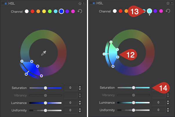
- When you move the outer wheel (target color) [15], the color range of the inner wheel does not change [16]. Moreover, the color of the channel [17] does not change, but the perimeter of the color turns white [18], indicating that the target color has changed. But the sliders below the wheel display the changed target color [19].
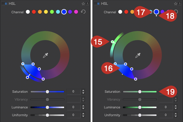
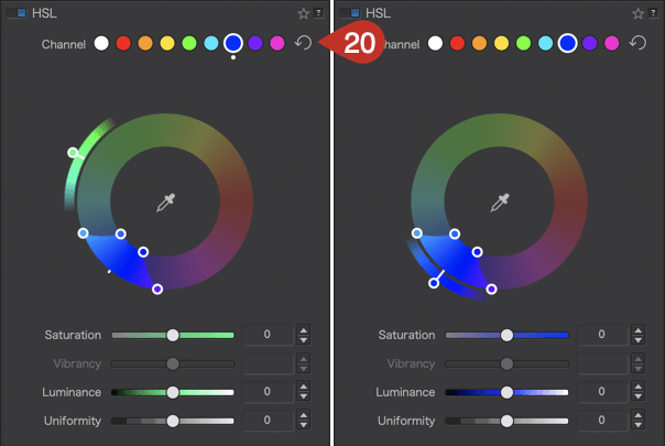
- To reset, click on the circular arrow [20] to the right of the channels. The channel, outer wheel, and inner wheel return to the color channel you initially selected, and the white dot disappears.
Please also note the following behaviors:
- When double-clicking a color channel dot, the specific color range and settings are reset.
- When dragging the start and end color range internal handles, the transition external handles will follow.
- Use the Alt key to independently modify internal color range handles.
- When moving the Hue (external wheel), the color range handles are temporarily hidden until you release the mouse button.
Sliders
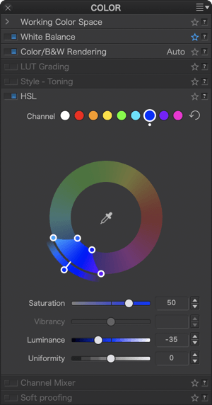
You can use the Saturation, Luminance, and Uniformity sliders to refine the color corrections you make with the DxO ColorWheel. All sliders are set to and remain at 0 by default, regardless of the ColorWheel settings.
The Saturation and Luminance slider bars show the target hue. For example, if you click on the blue channel, or if you have positioned the outer wheel handle on the blue (at 90°), the Saturation and Luminance slider bars will turn blue. If you change the target hue, the color of the sliders will also change to match the target hue.
Saturation
The Saturation slider subtly attenuates or strengthens all the colors in the image if the Global channel is selected, or the active hue channel.
If you move it to the left, the colors or the selected hue gradually shift to grey, and completely when you reach a value of –100. To the right, the colors or the selected hue become more and more vivid, but without the risk of clipping or oversaturating the color. The default setting is 0.
Vibrancy
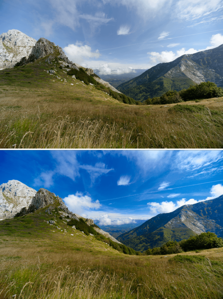
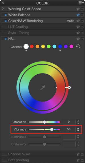
Compared to the Saturation slider, which reinforces colors, the Vibrancy slider operates in a much more subtle way, taking into account the vibrancy of the different colors in the image. It can be defined as a “smart” color saturation setting. The range is from –100 to 100, and the default setting is 0. When the slider has a positive value, vibrancy increases the overall saturation, but with some very particular behaviors:
- Skin tones are protected to avoid red faces.
- Blue sky tone saturation is increased and slightly darkened than for the rest of the colors in the image, to give greater presence and depth to the sky.
- Tones already close to gray are not affected, to avoid a change of color balance.
When the slider has a negative setting, overall saturation is reduced, with the following restrictions:
- Desaturation never reaches zero (i e. a black and white image), unlike the heaviest of HSL corrections.
- Desaturation is more pronounced in the reds, which is useful for “rescuing” photos in which the faces are too red, and for making skin tones more natural.
Luminance
The Luminance slider affects the brightness of the selected or active hue. By moving it to the left (dark end), you darken the hue and, to the right (light end), you make it brighter, while preserving the saturation as much as possible.
Uniformity
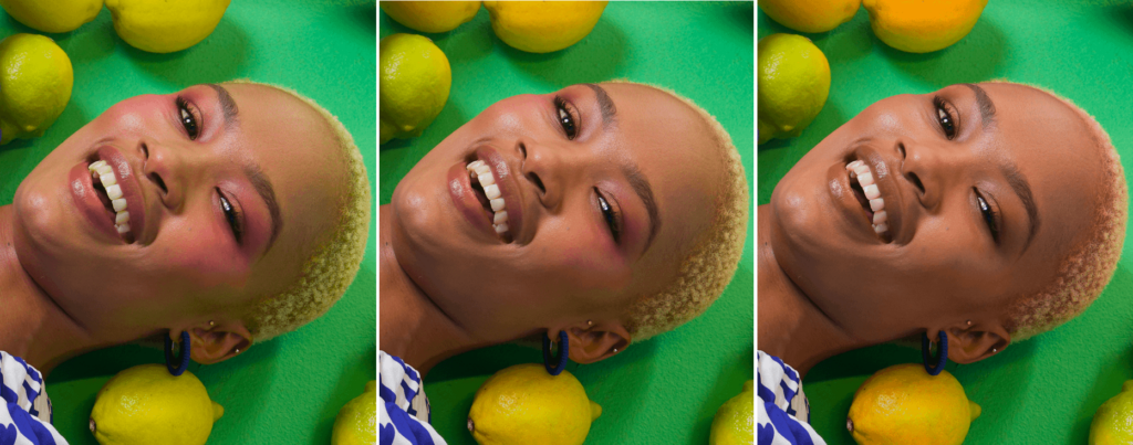
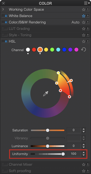
The Uniformity slider allows you to influence the color homogeneity of a defined and active range. Increasing the value (to the right) will reduce the shade variations of the target hue. Reducing the value (to the left) will increase the shade variations within the active range.
The algorithms that the HSL tool uses are not implemented by the Saturation and Vibrancy sliders (global & local settings), nor by the Hue slider (local settings).
Color sampler
You can also select a shade even more precisely with the Hue picker tool, found in the center of the DxO ColorWheel. It works with each of the color channels except the Global channel (white tile). To use the hue picker:
- In the HSL palette, select the desired channel.
- In the center of the DxO ColorWheel, click on the eyedropper to activate it.
- Click on the desired hue in the image.
- The corresponding shade range is automatically activated in the DxO ColorWheel.
- Make your shade and color adjustments using the DxO ColorWheel and associated sliders.
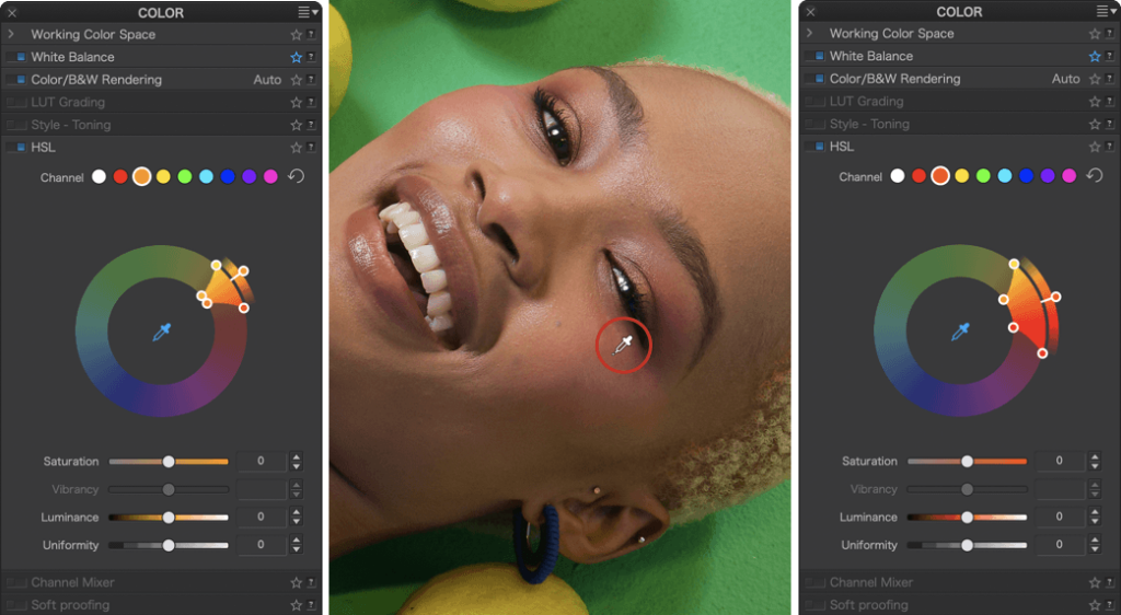
When you activate the hue picker, a toolbar is displayed below the image (Mac), or above (PC) and includes the following items:
- Name or icon of the active tool (hue picker).
- The selected channel and then the hue after modification are indicated (Mac).
- Radius: Allows you to adjust the hue picker’s sampling diameter from 1 to 50 pixels (the sampling area is indicated by a circle at the tip of the eyedropper).
- Reset button (Mac) or icon (PC): Resets the sampling; the indicator [2] returns to the base color of the selected channel.
- Close (Mac): Deactivates the hue picker (but not the corrections).

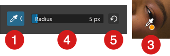
Display mask for the selected color range
After selecting a color channel by clicking on one of the pads (and possibly refining the selection with the eyedropper), you can display only the colors concerned by clicking in the range of the DxO ColorWheel, while holding down the Ctrl (PC) or Cmd (Mac) key. The rest of the image and colors outside this range will be shown in grayscale.
This method will allow you to select the colors to be processed even more precisely, since their display will vary depending on the settings you make in the DxO ColorWheel, both in terms of range and hue transitions.
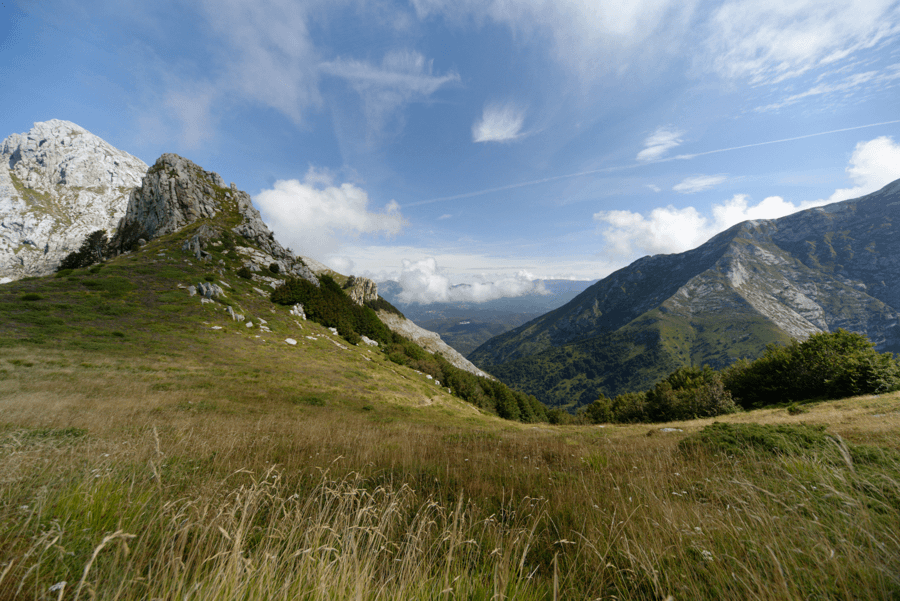
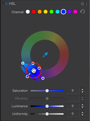
Channel Mixer
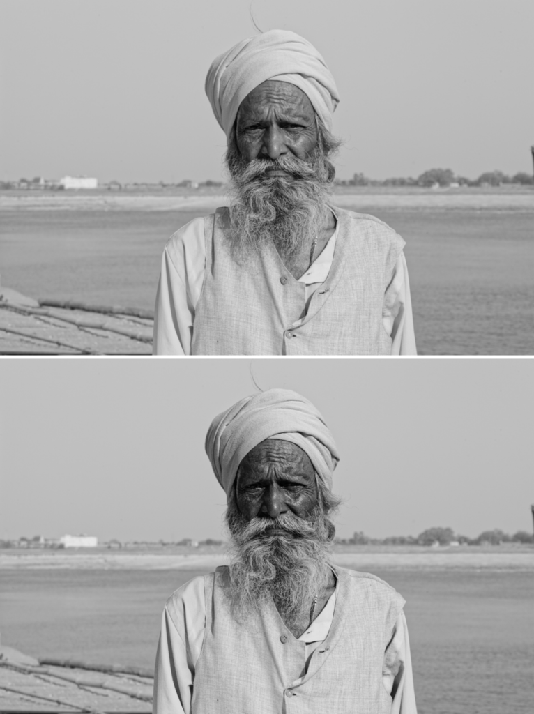
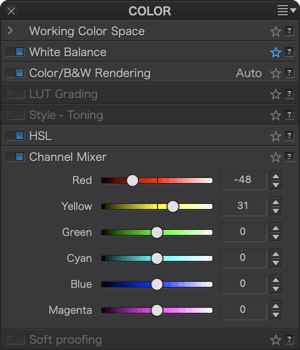
The Channel Mixer lets you adjust and fine-tune color and black & white pictures according to your taste by acting on the additive colors (red, green, and blue) as well as on the subtractive colors (cyan, magenta, and yellow).
You can think of the Channel mixer as a set of fully-configurable filters. Although the filters in the Filter palette are limited both in hue and intensity, the Channel mixer lets you create any combination of colors at any level of intensity.
To use the Channel mixer, you will need to evaluate which channels are too bright or too dark, and then move the corresponding sliders in the desired direction. For example, if your image contains yellow elements, you can move the Yellow slider to the left to darken them, or to the right to brighten them.
Soft proofing (ELITE edition)
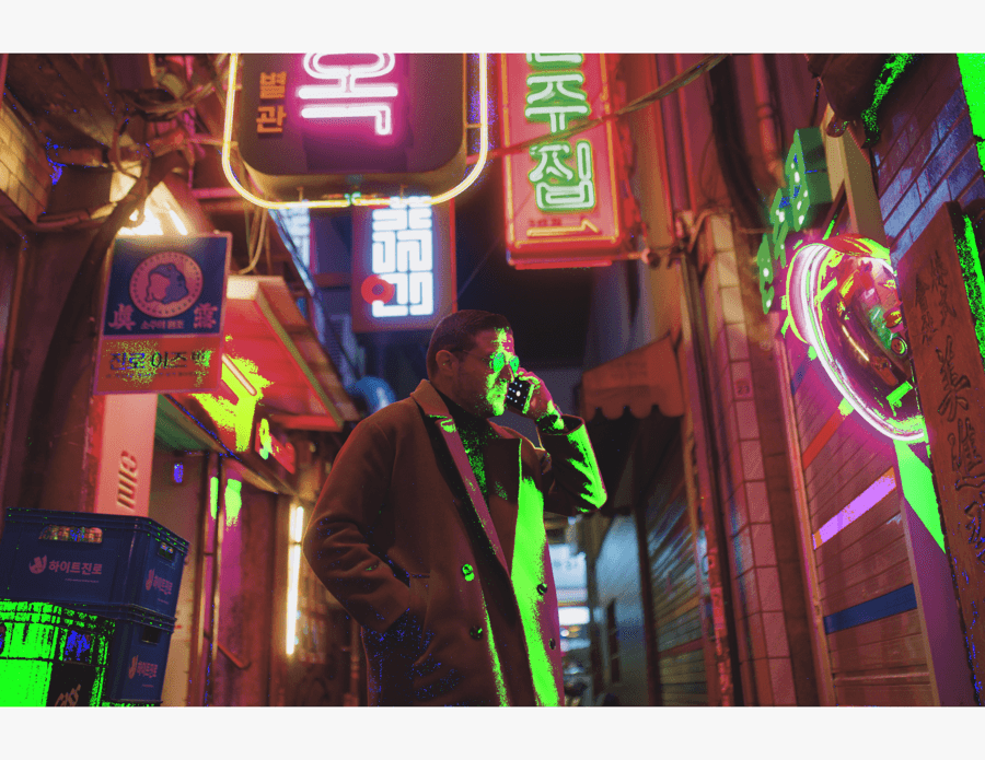
About soft proofing and recommendations
Screen proofing, or soft proofing, consists of simulating the rendering of a paper print on your screen, taking into account paper characteristics, such as its tint, as well as inks used by the printer or lab. This simulation, based on ICC colorimetric profiles, also lets you identify possible off-line (non-printable) colors as well as any corrections that may to be made before you start printing.
Soft proofing is not limited to printing, it also lets you simulate specific display renderings for where you plan to present your images (TV, tablets, etc.).
DxO PhotoLab lets you test on screen using ICC and CMYK profiles installed in your system, having obtained them from the following sources:
- When installing the driver for your printer.
- Website of the printer manufacturer for paper profiles not supplied with the driver (special papers, high quality stock, etc.).
- Website of paper manufacturers.
- Websites of publishers, graphics labs and printers in general.
All sites offering download profiles offer detailed installation instructions. This is done at operating system level, and DxO PhotoLab will be able to offer them to you and display them without you having to do anything special within the program itself, simply reach them through the Profile menu, in the soft proofing subpalette.
IMPORTANT: For soft proofing to be reliable and efficient, it goes without saying that your graphic chain – from the screen to the printer – must be calibrated using the corresponding tools (for colors and associated software), with screen adjustments (brightness, contrast, color temperature) set for printing. Also note that calibrations need to be updated regularly and, for an optimal result, must take into account the brightness and neutrality of your working environment. Do not hesitate to consult specialist sites and books, as well as the documentation of the manufacturers of this type of equipment.
Soft proofing Tools
Soft proofing is done in the Customize tab where the associated tools are to be found:
- Soft proofing subpalette in the Color palette.
- Histogram Palette and its color display buttons off gamut.
- White background of the image to simulate the visual impact of the white paper (also visible in the Full Screen Viewer).
Soft proofing Subpalette and White Background
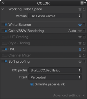
The Soft proofing Subpalette has the following elements:
- ICC profile: lists the ICC RGB and CMYK profiles installed on your computer, a list of main color spaces (sRVB, P3, Adobe RGB etc.) and a list of recently used profiles, which you can reset with the clear recent option. The Setup an ICC profile option lets you choose a profile installed in the color profiles system library.
- Mode: lets you choose one of the two rendering modes depending on the paper used or the lab or printer’s requirements. Perception mode lets you keep the proportionality between all colors displayed on the screen and those that are printable, this is the mode used by the majority of print labs. Relative mode also retains proportional values but links out of range colors to the closest printable colors.
- Simulate paper and ink: by checking this box, DxO PhotoLab will render a simulation of the look and feel of the paper for precise testing. This function works on the look of the white background that appears when you activate soft proofing.
- Preserve color detail: this slider applies only to matrix based ICC profiles, so only display profiles – not printer profiles. Set at 50 by default, the slider lets you alter saturation and details in saturated portions. By reducing the value (to the left), the slider maintains saturation to the detriment of the details and, To the right, the details are preserved to the detriment of the vivacity of the colors. Note that the Export menu has a Preserve color detail checkbox which gives you the option to apply the slider’s effect to the exported images.
Histogram out-of-gamut warnings
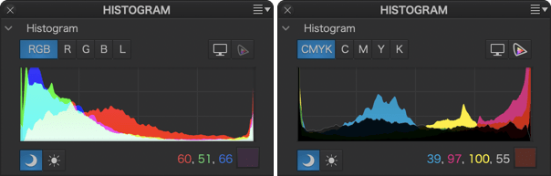
The histogram not only displays RGB or CMYK channels, depending on the selected profile in the Soft proofing subpalette, but also off-gamut warnings (out of color range) in the form of colored masks embedded in the image.
To do this, you have the following two buttons, which you can also use together:
- Show/hide the gamut warning screen: indicates the out-of-range colors for the screen as a blue mask on the image. As these colors cannot be properly rendered on the screen, they should be carefully considered.
- Show/hide destination gamut warning: indicates the off-gamut destination colors (e.g. non-printable colors with a particular ICC profile) as a red mask on the image.
Depending on the selected mode, RGB or CMYK, you can view the channels of the histogram by clicking on the corresponding buttons. This will let you determine which channel is affected by a gamut clipping or overflow problem, depending on the profile type:
- RGB: the 3 channels red, green, blue at the same time (RGB button) or separately (one of the buttons R, G, or B).
- CMYK: 4 channels Cyan, Magenta, Yellow, Black at the same time (CMYK button) or Separate (one of the buttons C, M, Y, or K).
Thumbnail Indications
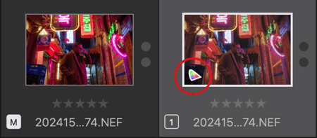
When you do a soft proof and apply an ICC profile to an image, a specific icon will be displayed in the bottom left corner of the thumbnail image. Hovering the mouse pointer over this icon will display a tooltip with the assigned profile.
The display icon is only visible if soft proofing is enabled, and also works on virtual copies.
Filtering and Displaying Soft proofs
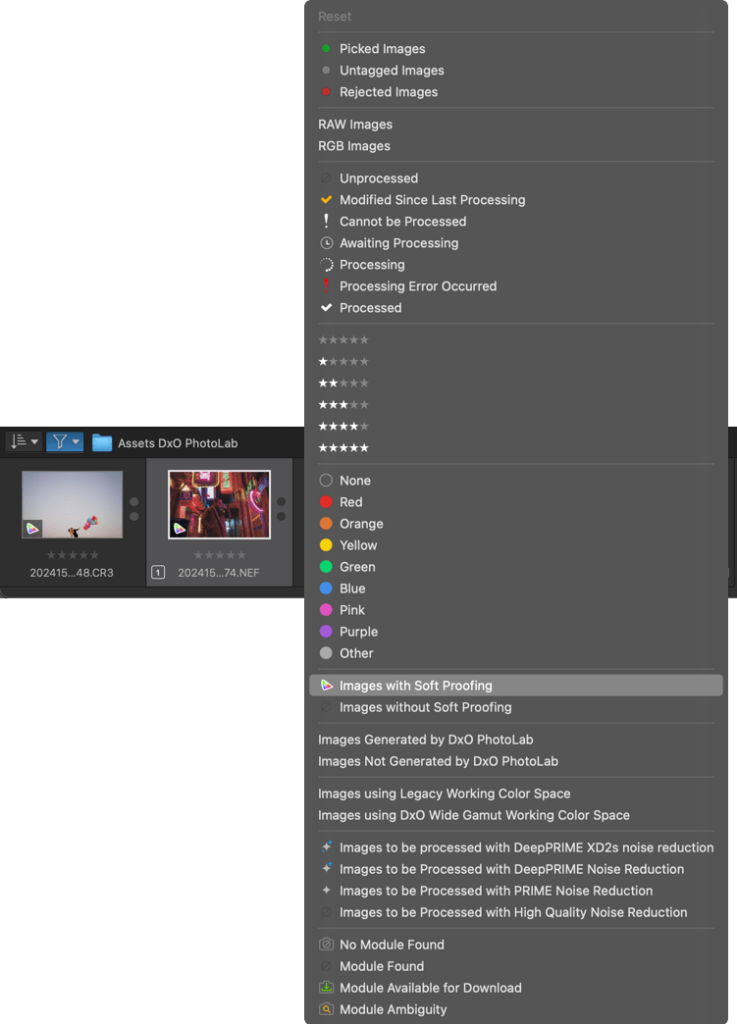
Image Browser allows you to filter images that either soft proofed or not. Click Image Filtering and select one of the following criteria from the list:
- Images with Soft Proofing.
- Images without Soft Proofing.
This way you can easily find the images with soft proofing and potentially group them into a project.
How to use soft proofing
We advise you to use virtual copies for all your simulation and soft proofing work. This will allow you to keep the master image, while creating multiple test copies with different profiles and/or renderings.
To do softproofing:
- Go to the Customize tab, then select your master image.
- A dialog box confirms that you are in soft proofing mode and invites you to create a virtual copy instead of using the master image (recommended workflow).
- In the Color palette, enable the soft proofing subpalette.
- Select the desired profile from the Profile menu.
- If the test is for printing, check Simulate Paper and Ink.
- In the Histogram palette, enable off gamut warning depending on the image destination: for screen (web display or on a particular device, tablet, mobile, etc.) or for a destination media (printing paper, publishing).
- If the image shows off gamut indications (blue for screen, red for paper), make the necessary corrections with the tools in the Custom tab (Saturation, Vibrance, TSL, etc.) to reduce non-printable colors. You can also use it to make any corrections that affect image rendering.
- You can also alter color saturation and detail in saturated areas with the saturated color protection slider in the softproofing subpalette.
- Once the corrections have been made and verified, you can leave the screen test on, especially if you are using virtual copies. This way you will always see the thumbnails with the test icon in your Image Browser.
Whether you turn the soft proof off or not, if you are printing it yourself it will be up to you to select the correct profile in the printer driver (the soft proofing does not convert your image).
When exporting images for your printer, follow their instructions as to whether you should attach the ICC profile or not (usually labs and printers do the conversion themselves).
If the profile used during the test is no longer available at the time of export, DxO PhotoLab automatically returns to the default sRGB profile, and an error message is displayed.
If you export images with a CMYK profile, they will be converted to CMYK. If the export takes place in the original folder or any folder managed by DxO PhotoLab, it will not be able to display them and you will not be able to correct them. A warning will be displayed instead of the image.
The Detail palette
Denoising & Demosaicing
The Denoising & Demosaicing subpalette contains buttons to access different noise processing modes and associated tools. Denoising can be previewed at 2 zoom levels with the Loupe tool.
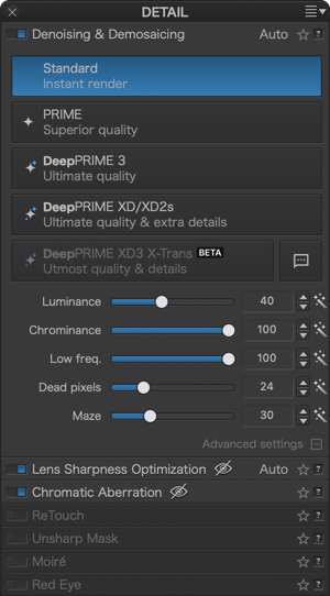
Selecting noise reduction modes
The mode selection buttons are greyed out when inactive and blue when selected and active:
- Standard.
- PRIME.
- DeepPRIME 3.
- DeepPRIME XD/XD2s.
- DeepPRIME XD3 X-Trans BETA
Noise reduction sliders and settings
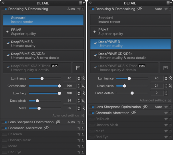
The Luminance slider is always accessible, you will need to click the + button (Mac) or Advanced Settings (PC) to display the other sliders. Some sliders are not available for RGB files:
- Luminance (RAW and RGB files): lets you smooth-out the grain (default setting: 40) to find a balance between granularity and conservation of detail.
- Chrominance (RAW and RGB files): adjusts the processing of colored parasitic pixels (default setting: 100).
- Low freq. (RAW files): slider attenuates low frequency noise which appears in the form of grain clusters (default: 100).
- Dead pixels (RAW files): reduces the effect of dead pixels on the camera sensor, visible as bright spots on the image (default setting: 24).
- Maze (RAW files): reduces the effects of “crosstalk” (default setting: 30), a phenomenon related to the way adjacent pixels capture light under certain conditions (small pixel size, flare, short distance between the sensor and the lens). Amplified by demosaicing, the phenomenon manifests itself as a 1 pixel wide structure resembling a maze.
- Force details (RAW files, DeepPRIME modes only): determines the threshold of detail by altering the noise mode used. Set to 0 by default, the slider will extract more details when moved to the right, towards a more natural rendering, when slid to the left the rendering will be softer, with fewer details.
In DeepPRIME modes, the Chrominance, Low Freq. and Maze sliders are not available.
Each slider has its own display and input fields; the magic wand to the right of each slider lets you return to the default settings at any time.
Thumbnail icons
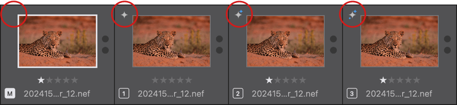
When you are processing images in one of the noise reduction modes, you will see an icon in the top left of the thumbnail. All modes, except Standard, have a unique icon (see picture above). The icon appears as soon as you select one of the modes, including before export, for PRIME and all DeepPRIME modes.
Loupe
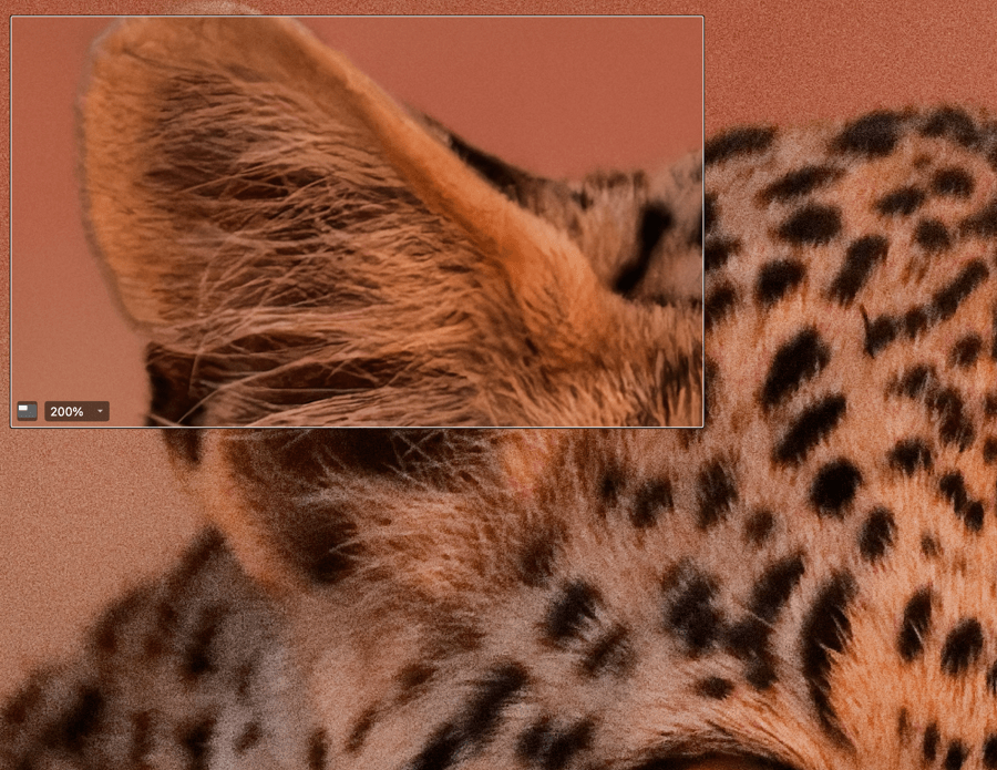
Denoising preview with the Loupe tool
The effects of the denoising modes and associated tools can be previewed only with the Loupe tool, except in Standard mode, which is also displayed in real time in the Viewer. To check the denoising:
- In the upper toolbar, click the Loupe button to activate it.
- Move the mouse pointer wherever you need in the Viewer, the loupe will refresh on the fly.
- You can set the zoom level, between 100% and 1600%. However, the best setting to check denoising is 100% or 200%.
- You can change the size of the loupe by clicking on the button in the lower left corner.
Standard denoising
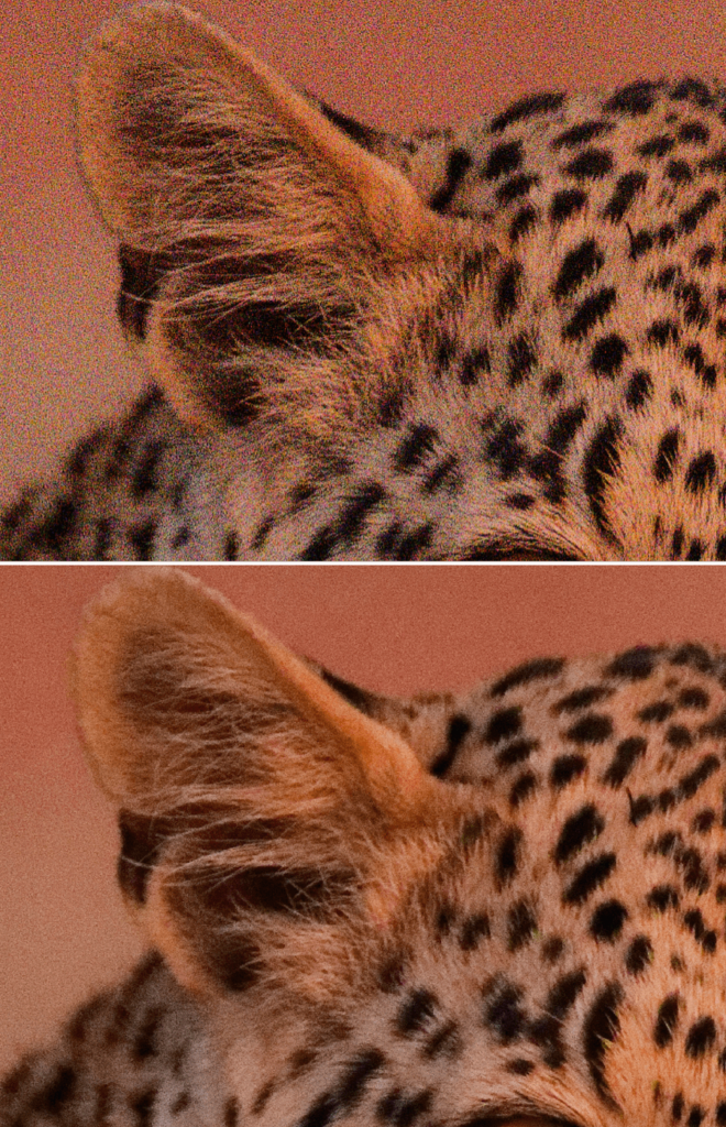
The Standard mode is applied by default with the DxO default rendering style.
How Standard denoising works
You can apply the Standard denoising mode to all files supported by DxO PhotoLab (JPEG, TIFF, RAW, and DNG). It offers the best compromise between quality and speed, and is automatically applied via the DxO Style – Natural preset when you open an image in the program.
Noise reduction is applied and displayed in real time in the Viewer, even when zooming and using the comparison tools. To judge the outcome, it is best to set the zoom to 100%.
All sliders are implemented, and DxO PhotoLab takes into account the characteristics of the camera, whose noise has been measured and characterized by DxO Labs, and of course, the ISO sensitivity you used. Even if, by default, the sliders display the same values, HQ noise reduction is not generic.
If you want to do the corrections manually, you will use mainly the Luminance and Chrominance sliders to adjust the ratio between granulation and detail, and the presence of colored pixels, especially in the dark parts of the image.
DxO PRIME denoising (Elite edition, RAW files)

PRIME or DeepPRIME?
Although DeepPRIME represents a great leap forward in terms of noise reduction technology and the quality of results, PRIME remains available in DxO PhotoLab for users of older computers that cannot meet the demands of current software, primarily in terms of processing and computing power.
How PRIME functions
The DxO PRIME noise reduction mode (Probabilistic Raw IMage Enhancement) applies only to RAW files. Its operation is based on the following principles:
- Applying a first denoising step to the image.
- Applying a second denoising step from the initial image, with estimation of similar elements detected after the most relevant analysis of the information (no averaging, since the content of the images is rarely constant), which leads to more intensive calculations.
Advantages of PRIME
DxO PRIME takes noise reduction even further, but with the aim of keeping as much detail and color in the image as possible. The advantages are:
- Noise-free images with vibrant colors, no aberrations, and perfectly preserved details.
- Takes advantage of the highest sensitivities offered by cameras, which opens up many new perspectives in the field of photography.
- Also enhances the processing quality of images taken at lower sensitivities, in which noise sometimes appears in shadows; it also has an impact on color saturation, which will be better preserved.
Images taken with older cameras, which are more prone to noise than newer models, also benefit from this technology. Finally, the higher the ISO sensitivity is, the more the difference in processing quality compared to the HQ mode will be perceptible. As a general rule, the divergence begins to be marked as early as ISO 1600, though this value may vary depending on the camera used and the image.
Drawbacks of PRIME
On the other hand, DxO PRIME implements complex algorithms that require a lot of computing power, which can lead to some constraints:
- Unable to display the result in real time in the Image Viewer, so preview is done in the Loupe tool.
- Not being able to display the result in the Viewer does not allow using the comparison modes to display before/after noise reduction.
- To judge the result for the entire image, you will have to export it and view it either in DxO PhotoLab or in any software capable of displaying photos. This process makes the workflow more complex and longer.
- The requirement to create an RGB file (TIFF or JPEG) thus implies the need for more storage space.
The processing time varies depending on the power of the computer and the size of the file, which can take from a few tens of seconds to several minutes, or even several tens of minutes for an older or less powerful computer.
Using PRIME
With PRIME, only RAW files can be processed:
- Select a RAW file.
- Activate the Loupe tool.
- In the Denoising & Demosaicing palette, click on the PRIME button.
- The content of the Loupe is refreshed and shows the result of denoising.
- To check other portions of the image, move the loupe through the image or click successively on the desired locations.
- Adjust the sliders as needed, they are all set to their default values, to which you can return by clicking on the respective magic wands.
- To check and definitively apply the PRIME noise reduction, proceed to image export.
If you want to compare the original image with its processed version, you can use the reference image mode to display both images side by side. Please refer to the Interface chapter to find more about the Compare and Reference image modes.
DxO DeepPRIME 3 and DxO DeepPRIME XD/XD2s/XD3 X-Trans Beta denoising and demosaicing (ELITE edition, RAW files)
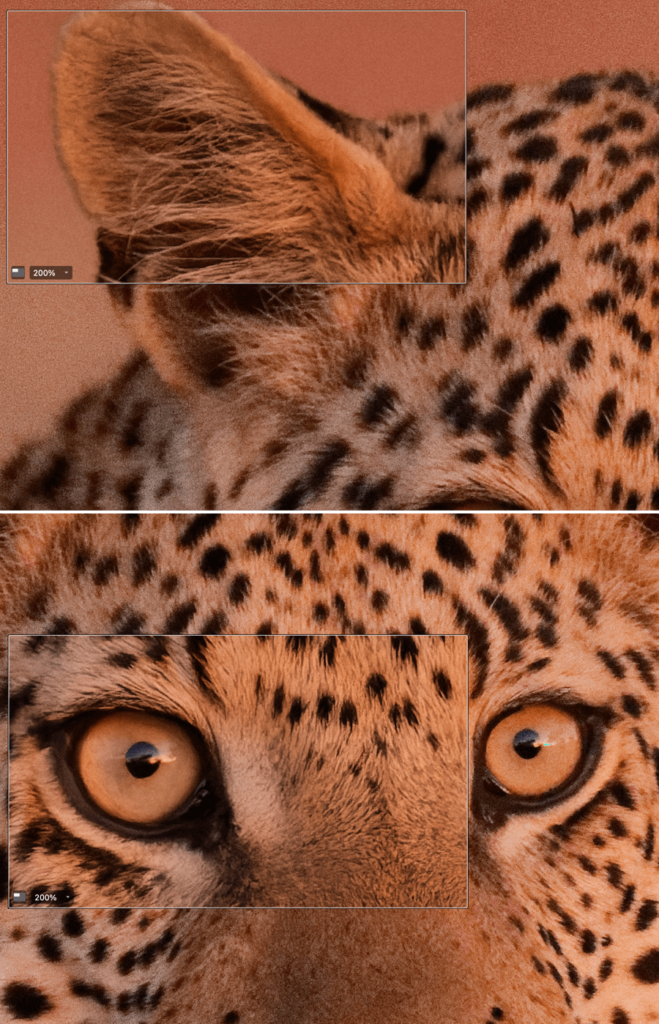
Image at ISO 7200: DeepPRIME XD2s
DxO DeepPRIME 3, DeepPRIME XD/XD2s and DeepPRIME XD3 X-Trans Beta (Deep, for deep learning, and derived from Probabilistic Raw IMage Enhancement) denoising and demosaicing technologies go even further in noise processing. Based on artificial intelligence and an extended neural network technology, their algorithms have been trained using billions of images produced by DxO over many years, for laboratory analysis. DxO DeepPRIME technologies use denoising and demosaicing in a holistic approach that consists of analyzing image problems in full context, rather than focusing solely on the problems of digital noise.
The advantages of DxO DeepPRIME technologies are:
- Exceptional image processing quality and noise reduction, with unparalleled preservation of detail and color.
- Pushing the limits of camera use, especially in terms of high ISO sensitivity.
- Gives new life and superior quality to digital images taken with older cameras.
The different versions of DxO DeepPRIME are:
- DeepPRIME 31: This method uses AI and deep learning technologies, and produces high-quality results, but faster than the other two methods. The third generation of DxO DeepPRIME is also able to correct chromatic aberration at the pixel level, without any colorshift.
- DeepPRIME XD2s/XD2: an advanced version of DeepPRIME that offers finer detail extraction. DeepPRIME XD2s goes even further with more details and no artifacts.
- DeepPRIME XD3 X-Trans BETA3: This is the next generation of DxO’s denoising and demosaicing technology, actually in development, and exclusively available, for the time being, to users of Fujifilm X-Trans sensors4. Denoising and details extraction reach quality levels never seen before.
1DeepPRIME 3 will be applied to Bayer and Fujifilm X-Trans Sensors
2DeepPRIME XD will be applied to Bayer and Fujifilm X-Trans sensors, DeepPRIME XD2s will be applied to Bayer sensor images only.
3DeepPRIME XD3 X-TransBETA will be applied, for the time being, to Fujifilm X-Trans sensor images only.
4At time of release (April 2025), DeepPRIME XD3 Beta doesn’t support 5th generation of Fujifilm X-Trans files yet.
Using DxO DeepPRIME denoising and demosaicing (RAW files only):
The computational power requirements mean you should use DxO DeepPRIME denoising and demosaicing on selected images, not on all of the images from a shoot.
- Select a RAW file.
- In the upper tool bar, cctivate the Loupe tool.
- In the Denoising & Demosaicing palette, click on the method of your choice.
- To check other portions of the image, move the loupe through the image or click successively on the desired locations.
- Adjust the sliders as needed; the Luminance, Dead pixels, and Force details sliders are set to their default values: 24, 40 and 0. You can return to the default values for Luminance and dead pixels at any time, with the magic wand.
- To check and definitively apply the selected denoising and demosaicing method, proceed to image export.
If you want to compare the original image with its processed version, you can use the reference image mode to display both images side by side. Please refer to the Interface chapter to find more about the Compare and Reference image modes.
Optimizing the performance of DxO DeepPRIME denoising and demosaicing
DxO DeepPRIME denoising and demosaicing takes advantage of the power of the graphics card (GPU) to perform its calculations and relieve the load on the processor (CPU). If your computer and its graphics card are compatible, the calculations are automatically taken into account. However, in the Preferences, you have a number of options:
- Mac: go to the DxO PhotoLab menu > Preferences > Advanced > DeepPRIME acceleration.
- PC: go to Edit > Preferences > Performance tab > DeepPRIME acceleration.
- Auto: Mode is automatically selected if the graphics card is supported.
- Use CPU only: lets DxO DeepPRIME denoising and demosaicing use the CPU rather than the graphics card, in case there are problems with it.
- Graphics card model name: if the computer has multiple graphics cards, the user can choose which will be used.
- Any changes to DeepPRIME acceleration preferences require restarting DxO PhotoLab.
- In case there is any incompatibility, the choices are disabled.
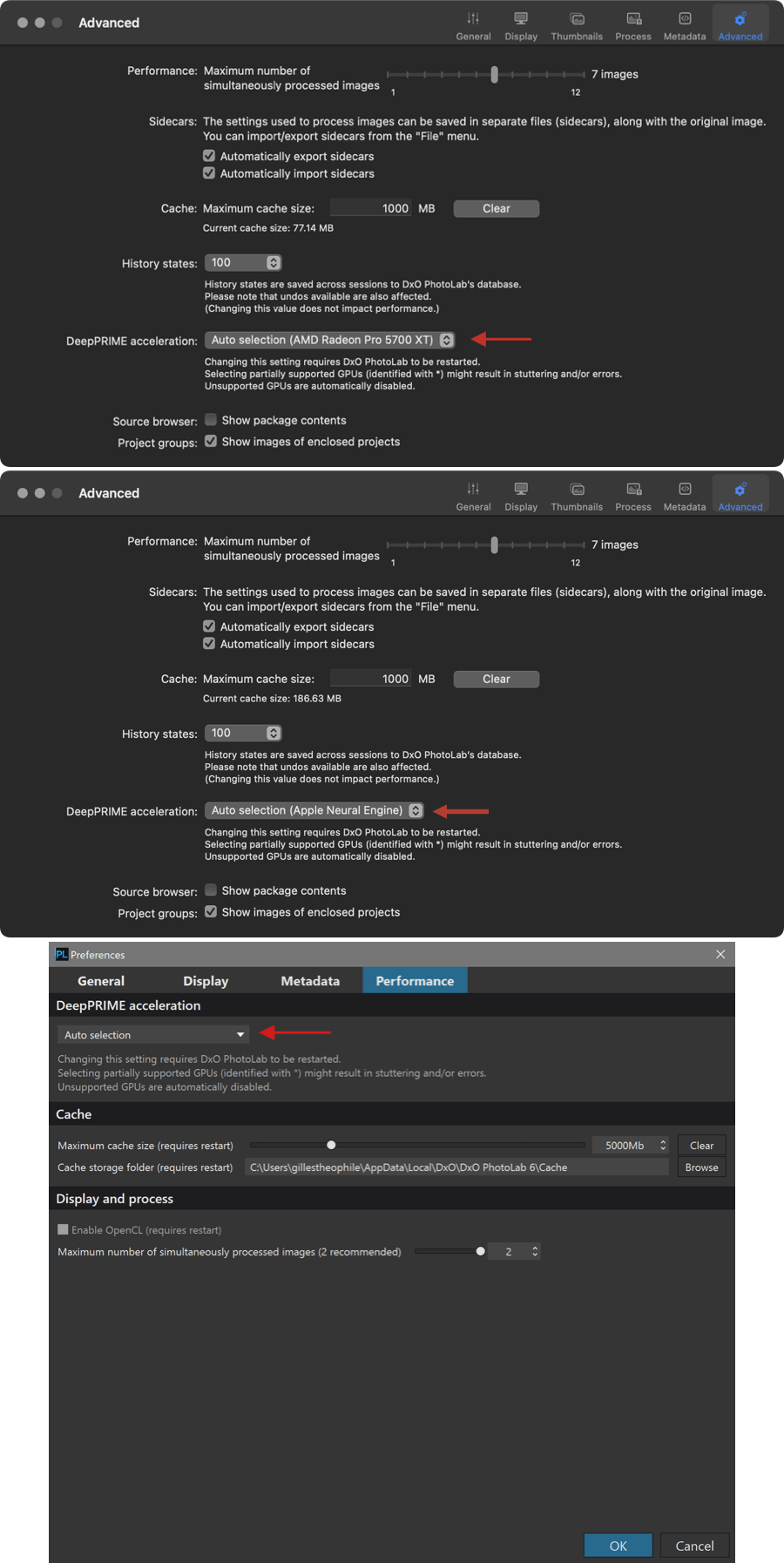
Lens Sharpness Optimization
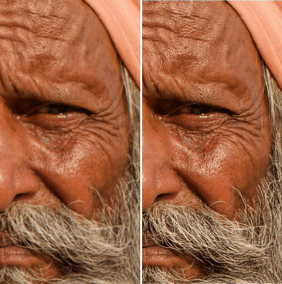
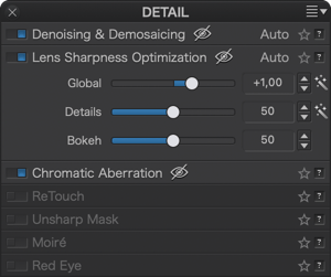
About optical sharpness
DxO PhotoLab’s exclusive DxO Lens Sharpness Optimization tool is one of its major strengths. Lens sharpness is an optical aberration which results in a point being transformed by the lens into a small blurred circle. (This should not be confused with out-of-focus or motion blur, which DxO PhotoLab does not correct.) DxO Modules have been created by measuring the amount of blur for every point in the image area for each supported camera body and lens combination. By combining the shooting parameters saved in the EXIF metadata (aperture, focal length, etc.) and the information provided by the DxO Module, DxO PhotoLab can apply corrections that are tailored to each pixel in the image. These corrections are not uniform, given that lenses are sharper in the center, which means that the pixels closer to the edges of the image will be subjected to a stronger correction than those near the center.
The Lens Sharpness Optimization sub-palette is visible only for images for which the appropriate DxO Module is loaded. If no module is available, you should use the Edge offset slider in the Unsharp Mask palette to manually adjust the sharpness in image corners.
- Global: Since DxO PhotoLab 6.3 (February 2023), the slider is set to +1,00 by default. The negative settings (from – 3 to 0) do not diminish the image sharpness, but result in more subtle corrections; in any case, the corrected image will be at least as sharp as the original. Even set at 0, the sharpness is greater than that of the original. To reduce sharpness (on a portrait for example) move the Global slider to the left; to increase it, move it to the right. The Lens Sharpness Optimization tool is what is known as an “intelligent” correction — one that is able to confine its effects to the noisy parts of the image, or when a photo was taken at high ISO.
It is important not to increase the sharpness of a shot that has already been sharpened by the camera, as is the case for JPEG images. So if you intend to post-process your images, you should shoot without any in-camera sharpening.
- Details: The Details slider is set at 50 by default and is used to enhance the micro-contrast of fine details in the image. This subtle correction can be very worthwhile for use in landscapes, but should be reduced to a minimum for portraits, where a certain degree of sharpness is needed to hide (for example) skin blemishes.
Unlike the Unsharp Mask tool, enhancing details with the Lens Sharpness Optimization tool does not create white edges or halos around the sharpened areas.
- Bokeh: The Bokeh slider reduces artifacts in the bokeh (i.e., the out-of-focus area in your photos, mostly in the background) that can appear when using the sharpening tools. However, the slider will also have an influence on the sharp portions of the image.
Lens Sharpness Optimization and Unsharp Mask
We recommend that you perform as much of your sharpening as possible using the DxO Lens Sharpness Optimization tool before using the Unsharp Mask. Of course, for images where the appropriate DxO Module is not installed, you will have to use the Unsharp Mask for all manual sharpening tasks.
Chromatic aberrations
About chromatic aberration
Chromatic aberration results from different colors focusing on slightly different places, In any case, this is a very visible problem, especially along objects and elements in a high contrast image
: green and red fringes (lateral aberrations), just green or purple fringes (longitudinal aberrations). A particular phenomenon that is also mostly due to chromatic aberration, “purple fringing” is when a ghost-like purple image appears along highly contrasted edges.
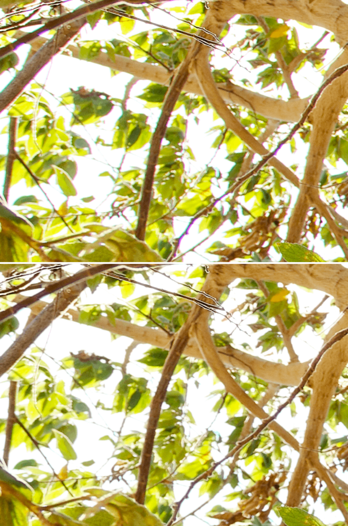
Correcting chromatic aberrations
Lateral chromatic aberration (e.g., magenta or green fringes along edges) is automatically corrected only if the appropriate DxO Module is available. In this case, no further manual action is necessary.
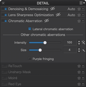
You can correct the other types of chromatic aberrations (longitudinal or other) using the two sliders in their respective sections of the palette:
- Intensity sets the strength of the correction, within a range of 0 to 200.
- Size: adjusts the width of the colored fringe to be suppressed, within a range from 0 to 12 in arbitrary units. This setting affects how DxO PhotoLab determines the chromatic aberration to be corrected, and what is real image content.
You should check the Purple fringing correction box for all backlit scenes, or when shooting with a lens prone to this optical defect.
ReTouch Tool
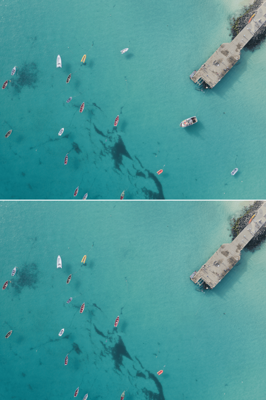
Overview
The ReTouch tool (formerly known as the Repair tool) not only lets you clean-up marks and dust from the camera’s sensor, but also remove unwanted elements from the image, with a level of control that forgoes the need for retouching software in most instances. The ReTouch tool includes the following:
- Brush tool for adding or erasing a stroke, with maximum accuracy.
- Transform tool to change the portion of the image selected, vary its size, proportions, or invert it.
- A Repair mode, to correct a portion of the image and embed the repair in the image, and a Clone mode, to duplicate a portion of the image to apply it elsewhere.
Interface

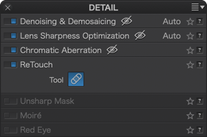
The ReTouch tool is located in the Customize tab and can be accessed in two ways:
- From the button in the top toolbar.
- If the DxO Advanced workspace is enabled, in the Detail palette, under the ReTouch section.
The tools are located in an embedded settings palette to the bottom left of the image. A palette of keyboard shortcuts can also be found to the bottom right or, on Mac, in the toolbar under the image.
Mac version
The tools are available in the lower toolbar under the image, in the form of a palette of settings to the bottom left of the image and a collapsible palette of keyboard shortcuts to the bottom right.
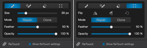
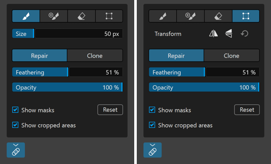
The tools are available in a palette of settings to the bottom left of the image, and in a collapsible palette of keyboard shortcuts to the bottom right.
The settings palette contains all of the tools, as well as their associated options (from top to bottom and left to right):
- Tool selection buttons: let you choose between the retouching brush for a new mask, the add stroke to alter an existing mask, and the erase stroke to partially or completely remove a mask. The last button activates the transformation tool.
- Size (when one of the 3 brush types is active): Adjusts the brush diameter.
- Transform (when the transformation tool is active): Displays vertical and horizontal flip buttons as well as a reset option.
- Repair/Clone buttons: to enable Repair mode (taking the brightness, contrast, and color of the image portion to be retouched into account) or Clone mode (duplicating by copying-pasting a portion of the image).
- Feathering: alters the hardness of the brush edges. The higher the value, the more diffuse the edges of the repair will be so as to better blend it into the image.
- Opacity adjusts the transparency of the repair. The highest default value is 100% (fully opaque); reducing the opacity makes the defect relatively more visible. The minimum opacity value is 10%.
- Display masks (PC): This checkbox displays blue masks for different corrections and retouches (you can also hit M to show or hide masks).
- Show cropped areas (PC): Display all of a cropped image. The out-of-frame areas are indicated by a dark translucent mask.
- Reset(PC): removes all corrections and retouching done with the ReTouch tool.
The lower ReTouch toolbar (Mac).

The lower toolbar contains the following options (left to right):
- Show ReTouch Tool Settings: by checking/unchecking this box you can show/hide the selection palette and tool settings (bottom left of the image).
- Show masks: This checkbox displays the blue masks of the various corrections and retouches.
- Reset: removes all corrections and retouching done with the ReTouch tool.
- Close: validates your corrections and retouches and closes the ReTouch tool.
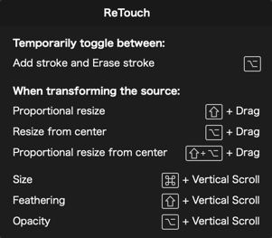
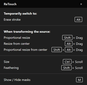
The palette of keyboard shortcuts can be opened or closed by clicking on the question mark to the bottom right of the image.
The brush
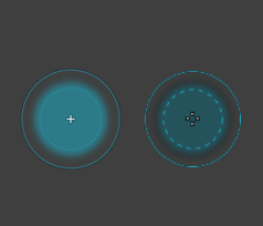
The circular-shaped brush is activated by clicking on the New Mask button in the floating palette to the bottom left. You can adjust its characteristics using the sliders for Size (diameter), Feathering (edge hardness), and Opacity (transparency of the repair).
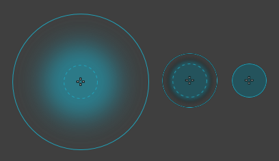
Center: size 100 px, feathering 50 %, opacity 100%.
Right: size 100 px, feathering 0%, opacity 100%.
A New mask (first button) is made up of the following elements (from center to edge):
- A cross marking the center of the brush.
- A dashed circle and a translucent blue mask representing the brush and its area of application for the correction, according to the opacity setting.
- The gap between the dashed circle and the outer circle will depend on the feathering setting.
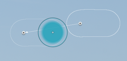
Add stroke mode (2nd button) lets you enlarge an active mask. It has the same appearance as the brush in New mask mode, but is distinguishable by the following element:
- A black pictogram with a + (plus) sign.
Erase stroke mode (3rd button), lets you erase all or part of the active mask, and appears as follows:
- Looks the same as in New mask mode, but with a white mask and white circles instead of blue.
Erase stroke mode.
The masks
When you are doing a repair, provided they are set to display, the masks are represented by white outlines (a circle in the case of single click with the brush) with a circular tile in the center which will vary according to the situation:
- Translucent central tile: inactive, unselected, repair mask.
- Opaque central patch and thin mask outline: Repair mask selected and active.
- Opaque central patch and thicker mask contour: Sample area of the repair, connected to the repair mask by an arrow (the arrow points from the sample area to the area to be repaired).
The shape of the mask is invisible when it is inactive (translucent tile). Move your mouse pointer over the circular tile to see it. This avoids unnecessary cluttering of the image if you have applied lots of retouching masks.
To fine-tune or resume a repair, you can move the repair mask or the sample source, or both, by clicking on their respective patches to activate them. The mouse pointer changes to the Hand tool as soon as you place it on one of the patches.
You can also change the settings of the feathering and opacity sliders. In which case, the repair area mask will display any changes to these settings in real time.
For better clarity and visibility, the shapes of any inactive masks are not displayed. Only the circular tiles are visible, as well as the shape of the active mask.
To move a circular tile associated with a repair mask and/or sampling mask: activate the repair mask by placing the mouse pointer on the tile (which temporarily becomes the Main tool) then reposition it as you wish by dragging-and-dropping. This option to move masks around helps you refine or restart a repair.
To delete a retouch mask:
- Click on a mask to activate it and then press the Delete key.
To remove all the masks at once:
- Click the reset button, in the top right hand corner of the screen (PC) or click Reset in the lower toolbar (Mac).
The Transform Source Tool
With the Transform source tool, you can go much further with the precision and finesse of your repairs and retouching. Indeed, you can do the following with the transform tool:
- Enlarge the source area.
- Rotate the source.
- Resize the source proportionally and/or from its center.
- Flip the source horizontally and/or vertically.
The transform box, once activated, appears as a dashed rectangle that covers the source mask for the repair or retouch. The transform box has 8 anchor points, 3 on each side with 1 on each corner. How the anchor points work will also depend on which keys are pressed:
- Side anchor point: only affects the side.
- Corner anchor: adjusts the size of the box according to the direction the anchor is dragged.
- Anchor + Shift key: changes the size of the box proportionally.
- Anchor + Alt (PC) or Option (Mac): adjusts the size of the box relative to the center (the central tile does not move).
- Anchor + Shift + Alt/Option keys together: adjusts the size of the box proportionally, relative to its center (the central tile does not move).
To invert the transform box, click on one of the flip Icons in the floating palette. To reset it, click on the curved arrow.
Using the ReTouch tool
Cleaning up dust and marks from the sensor
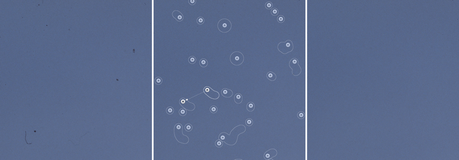
The ReTouch tool is ideal for cleaning away marks and dust that came from the sensor, on the image. All you have to do is use the following steps:
- Activate the ReTouch tool.
- Zoom in on the image to at least 1:1.
- In the Move/Zoom palette, move to the top left of the image.
- For effective cleaning, set the tool to Repair, Feather 100%, and Opacity 100%.
- Place the brush over a mark and adjust the size to cover it completely.
- Click: the mark is removed, active masks (sample source and repair area) are indicated by an opaque tile connected by an arrow (pointing towards the repair area).
- Proceed to the next specks or defects and repeat steps 5 and 6 as many times as necessary.
- When you are done cleaning a portion of the image, use the frame in the Move/Zoom palette to move to another spot (you can also move the image by using the Space bar to temporarily enable the Hand tool).
- Continue to clean the image one area at a time until you finish at the bottom right of the image.
- Click Close to exit the ReTouch tool.
Better visualization of dust and marks
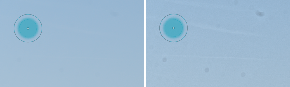
Sometimes dust that is barely visible on the screen can be seen in the output document, especially when printing. Tip: To more easily identify marks and dust, temporarily alter the contrast, using Microcontrast or DxO ClearView Plus (ELITE edition). With major adjustment, these tools will enhance the contrast of the details and therefore reveal defects that need to be retouched. Once your repairs are made, return the contrast tools back to their default settings.
Retouching skin
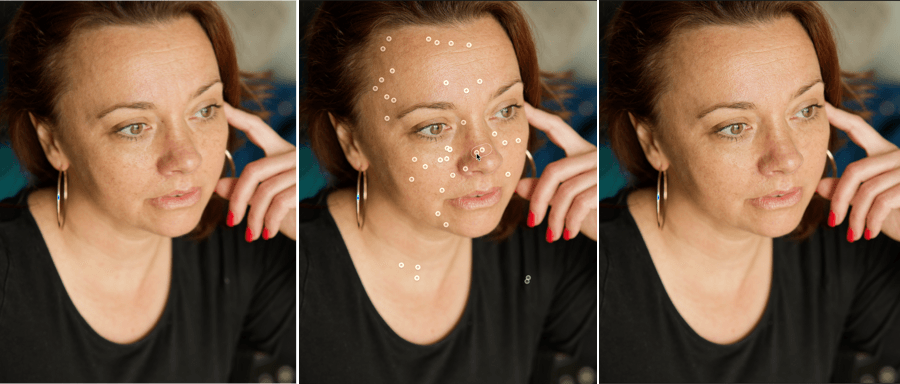
The ReTouch tool is also useful for cleaning up skin blemishes. For example, you can remove or attenuate details such as moles, freckles, acne, beauty spots, scars, wrinkles, crows feet, rogue hairs, etc.
When retouching a face, you should not attempt to remove details that distinguish the person, that are integral to their visual character, such as a moles or wrinkles. However, you can reduce their visual impact slightly using the Opacity slider.
Repair or Clone?
In most cases you will use Repair mode, which takes into account characteristics such as the luminosity, contrast, and color of the image portion for cleaning or retouching, as this will blend well with the rest of the image.
However, Clone mode will copy an element of the image so you can easily rebuild portions of images that contain well-defined structures or textures. Furthermore, the adjustment of mask size, proportion, and inversion offered by Transform mode will help you attain a high level of accuracy in your retouching tasks.
Batch repairing and retouching
If a number of images share the same defect, you can do the following:
- Using the ReTouch tool, repair, clean and retouch the first image.
- Right-click on the image and then select Copy correction settings from the context menu.
- Select the target images.
- Right-click on the image selection and choose Paste correction settings > Paste all correction settings in the context menu.
- In the dialog box, make sure Detail > ReTouch is checked (as well as the other corrections you want to apply, otherwise select everything else).
- Click Paste.
- Your corrections and retouching are applied to the destination images.
For best results, only correct defects located in the same location on each image. If there are framing and orientation differences from one image to the next, you will need to change the source sample.
Unsharp Mask
The purpose of the Unsharp Mask tool is to sharpen an image. The tool makes a blurred copy of the original picture, then subtracts the original from the blurred copy, leaving the finest details, which can then be enhanced.
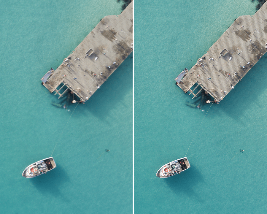
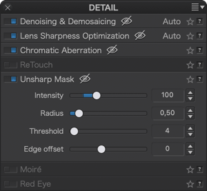
The Unsharp Mask palette includes the following four sliders:
- Intensity: sets the amount of sharpening to be applied to the whole image.
- Radius: sets the thickness of the edges to be sharpened.
- Threshold: sets the level above which details will be sharpened, and below which they will be left as they are, making it possible to avoid sharpening the smallest details that look just like noise.
- Edge offset lets you homogenize the sharpness between the center and the edges of an image.
75% zoom is the minimum level for working with the Unsharp Mask palette corrections; however, we recommend that you always choose to work using at least 100% zoom to ensure accuracy and efficiency.
Using the Unsharp Mask
The Unsharp Mask correction is disabled by default. It is unnecessary for JPEG files, as in-camera processing has already sharpened them, and it is usually unnecessary for RAW images for which a DxO Module is available. This means its use is really confined to unsharpened JPEG files and RAW files without a DxO Module. In the latter instance, we advise fine-tuning the Unsharp Mask settings, and then creating a preset.
We recommend that you try fine-tuning the three sliders using these starting values: Intensity = 100, Radius = 0.5, and Threshold = 4. For most images, Threshold should stay within a range from 4 to 10. Radius determines how subtle the correction is: excessive values will result in halos. Finally, you can set the Intensity slider up to 200.
The negative values in the Intensity slider (from -100 to 0) can be used to soften instead of sharpening an image (which can be useful for portraits).
You can deal locally with sharpness and blur with Local Adjustments.
Moiré (ELITE Edition)
Moiré appears as colored artifacts or patterns when fine, high-frequency details interfere with the camera sensor. This is particularly true for cameras with weak or no low-pass filters. The photos they produce are sharper than those taken with traditional digital cameras (which use strong bypass filters), but the risk of introducing moiré will be much higher. Moiré is especially apparent in image details such as tile roofs, wire fences, mesh, feathers, fur, hair, and fabrics.
The Intensity slider helps to reduce or recover these artifacts. Its range goes from 0 to 100, with 99 as the default value in auto mode. After any adjustments, you can reset to the default value by clicking on the magic wand.
The effect of this tool can be previewed only if your image is displayed at 75% zoom or higher.
Correcting red-eye
Red-eye correction is fully automatic, although there is also a manual mode to use in cases when the automatic mode does not detect the problem. You can use the tool with RAW and DNG files, as well as with JPEG and TIFF files. The Red-eye sub-palette in the Detail palette
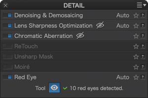
To activate automatic correction, click on the Red-Eye button, either in the upper control bar or in the Red-eye sub-palette of the Detail palette. The correction is controlled by selection ellipses around each red eye detected in the picture. (with the number of red eyes shown in the sub-palette).
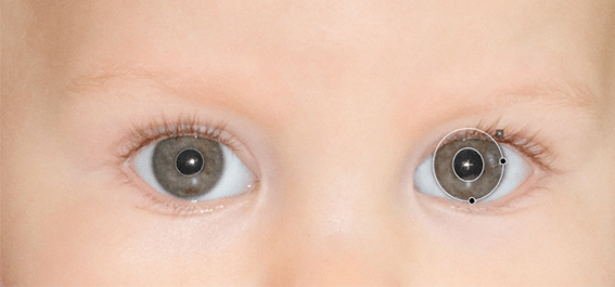
Rolling the mouse over the ellipses activates them to perform the following operations:
- Moving
- Change the size in a horizontal or vertical direction using one of the two handles
- Rotation using one of the two handles
- Deletion by clicking on the cross at the top right, outside the ellipse.
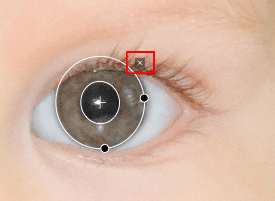
If the tool does not detect red-eye because of the orientation of the face or the instance is too small, it will show the message “No red-eye detected” in the sub-palette. In this case, you can make the corrections by hand:
- Activate the Red Eyes tool in the command bar or sub-palette.
- Draw a selection rectangle on an eye.
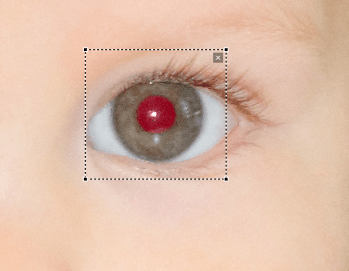
- The correction is applied automatically, which is confirmed by the ellipse that replaces the selection rectangle.
- Make any necessary adjustments (position, size, orientation of the ellipse).
- Move on to the next eye, and so on.
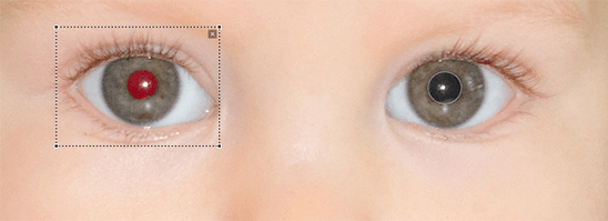
The toolbar below the image allows you to enable or disable the display of ellipses (also called pupil areas), reset corrections, and close the tool.
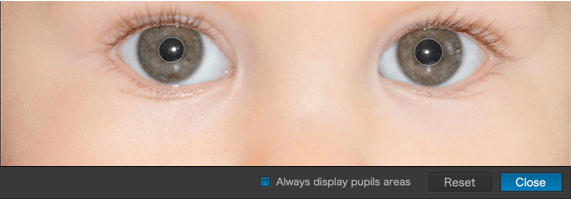
The Geometry palette
Focal length and Focusing distance
The lens focal length and focusing distance of a photo are recorded in the EXIF data of your images. However, this information is not always accurate. For example, different but close positions of the focal length ring (say, 17 and 18 mm) could result in the same value (say 18 mm) being recorded in the EXIF data. In this case, the distortion correction may be less than optimal. In the same manner, the focusing distance might be recorded in the EXIF data with insufficient precision, and similarly lead to an imprecise correction. In both cases, to improve the effectiveness of the optical corrections, you can provide more accurate values in one (or both) of the sliders that appear in the Geometry palette:
- Focal length: Use the slider to specify the lens focal length.
- Focusing distance: Select a range for the focusing distance in the drop-down menu, then fine-tune with the slider.
The Focal Distance and Distance focusing sliders are permanently displayed in the Mac version, and appear automatically in the PC version.
Horizon
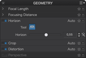
The Horizon tool lets you automatically or manually straighten out a slanted image.
You can also right the horizon with the crop grid (Crop tool).
Automatic mode:
- Click on the magic wand to the right of the Horizon slider.
- To cancel the automatic correction, click again on the magic wand.
- To modify or fine-tune the correction, use the Horizon slider.
Manual mode:
This user-friendly tool, also available in the command bar, lets you easily straighten out a tilted horizon.
- Click on the Horizon button.
- Superimpose the reference line on the tilted horizon by placing the anchor points on the desired areas.
- You can also trace a new reference line in the image and refine its position by moving the anchor points to the desired locations.
- If you have enlarged the view by zooming in, you can navigate in the image by using the Move/Zoom palette.
- Click on the Preview button on the lower right, underneath the image, to return to the default view.
- You can cancel the correction and start over by clicking on Reset.
- Confirm the correction by clicking on the Apply button.
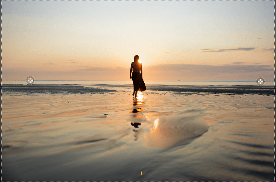
The Horizon tool is just as practical for applying small rotations (less than 5%) to your image. To do this, you can use the slider or enter a value.
Crop
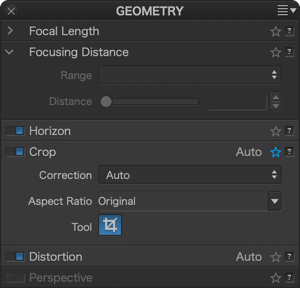
Automatic cropping
An image whose perspective has been corrected by the Horizon/Perspective tools generally loses some information at the edges – a great deal more if the correction is significant. This is why the Crop palette is set to Auto based on Perspective / Horizon by default, and the aspect ratio is set to Original, meaning that cropping is performed automatically on the corrected image while retaining as much information as possible.
- Selecting Original in the Aspect Ratio drop-down menu instead of Unconstrained will resize your image while maintaining its proportions (i.e. the relationship between its longer and shorter sides: for example 3:2 or 4:3).
- It is also possible to choose a different ratio in the Aspect ratio drop-down menu, such as 1:1 (a square format), 5:4 (replicating the traditional 5×4 or 10×8 format), or any other in the list.
The grid display is activated by default.
Manual cropping
The lower toolbar

When you activate the Crop tool by clicking on the Crop button in the upper toolbar, another toolbar appears just below the image. This one contains the following options (from left to right):
- A menu for selecting predefined aspect ratios (or ratios) (1:1, 16:9, etc.), set to Original by default (the original aspect ratio of the image is retained).
- The buttons to rotate the image by 90° increments to the left or right (also available in the Image > Orientation menu).
- A slider that allows you to set the opacity (at 50% by default) of the areas that will be lost when cropping.
- The Show grid checkbox, which allows you to show or hide the crop grid.
- The horizontal and vertical dimensions (in pixels) after cropping the image. Note that these numbers vary in real time during cropping operations.
- The Reset button to cancel the cropping.
- The Close button to approve the cropping and to exit the tool.
Straightening the Horizon
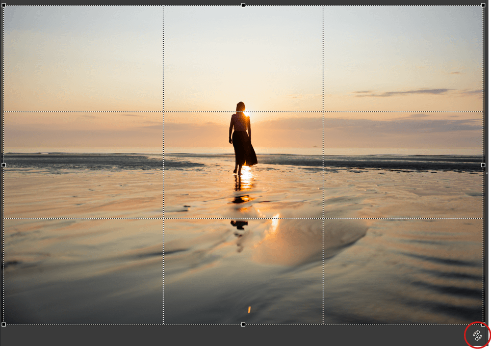
Whether you are auto-cropping or manually cropping, you have the option to straighten the horizon directly, without having to go through the Horizon tool:
- Place the mouse next to one of the four corners of the cropping grid and a double curve will appear.
- Press the left mouse button and rotate in the desired direction.
- Use the grid as reference if you want to straighten the horizon.
Cropping manually
If you click on the Crop tool button, a dotted-line crop box will display on the image. You can move or extend this box by dragging its corners. If you have chosen a specific aspect ratio, the box will display the proportions of this aspect ratio, and you will be allowed to change only one of its dimensions, the other tracking automatically. If you have chosen an unconstrained aspect ratio, you will be able to freely change both dimensions of the box.
You can also draw the cropping frame yourself by clicking and dragging on the image while holding down the left button of your mouse. To change the size, simply grab the frame at the side or at the corner. If you grab one of the corners and you reduce the size of the frame to a certain point, it will switch from a horizontal to a vertical ratio.
You can move the frame around the image by clicking the mouse pointer inside the frame and dragging (a quadruple arrow will appear as the pointer).
Clicking outside the box removes the box and lets you create a new box from scratch.
If you have selected Unconstrained in the Aspect Ratio drop-down menu, holding down the Shift key will allow you to preserve the proportions.
From there, you can select a predefined aspect ratio, type in your own values, show or hide the grid overlay, reset and close the tool. When you manually crop, the dimensions in pixels are displayed in the lower-right corner of the frame.
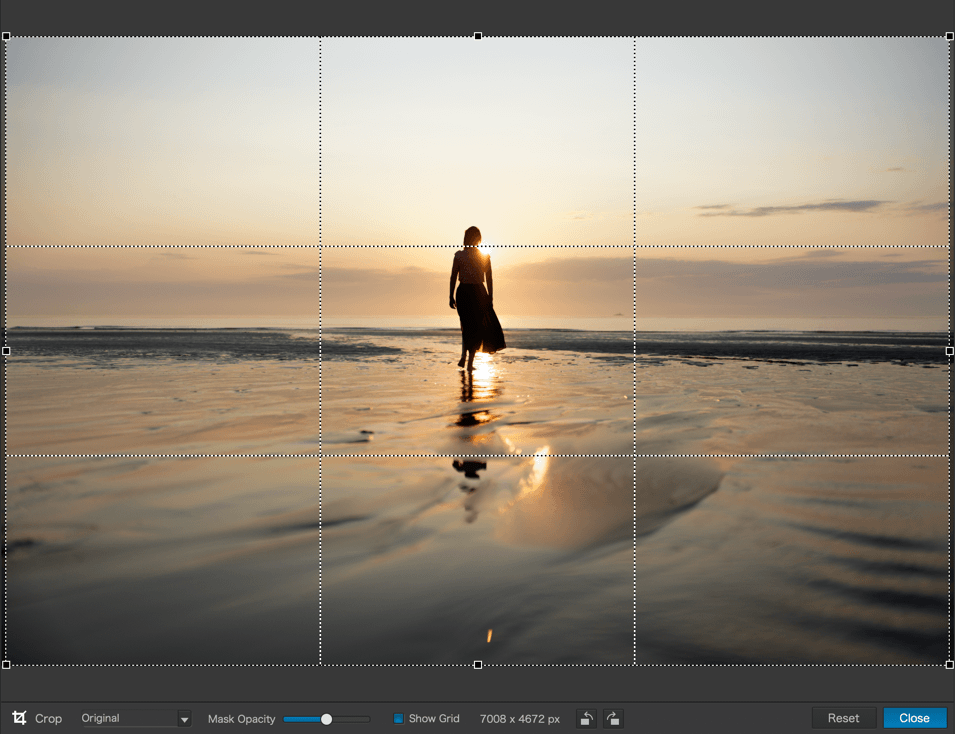
When the crop tool is active, a command bar is displayed below the Viewer pane. You can choose a predefined aspect ratio for your image, or enter a custom ratio, display or hide the “rule of thirds” grid, reset the crop, or close the tool.
You can apply the settings and close the tool by pressing the Enter key, or reset the crop and close the tool by pressing the Escape key.
Custom ratios
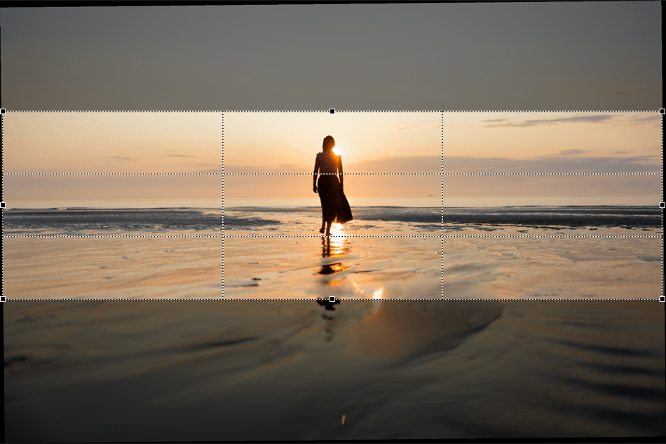
The custom ratio will allow you to crop your image according to a format that you would need to (for example) publish on the web, in a book, or simply, for making a print according to the dimensions proposed by a photo lab. In these cases, you will be able to recompose your image exactly as you will see it after publication or printing, without any unexpected surprises. Here, we will use a panoramic format of 175 x 50.
PC
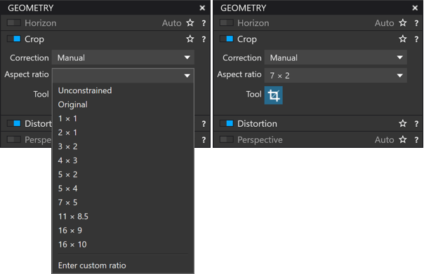
To apply a custom ratio:
- In the Crop subpalette, as well as in the toolbar under the picture, select Enter a custom ratio from the Aspect Ratio menu.
- Enter 2 values, width and height, separated by x or a / (175×50 or 175/50 in our example), then hit Enter.
- The cropping grid adopts the entered ratio, whose values are displayed in the Ratio menu. You can fine-tune the framing and composition of your image so as to be certain that it will be published or printed as desired.
To delete a custom ratio:
- Open the Ratio menu. In the Enter Custom Ratio section, place the mouse over the ratio to be deleted.
- The ratio is highlighted and a trash can appears to the right of it. Click on the trash can to delete the ratio. (Note that you cannot delete ratios other than custom ratios.)
Mac
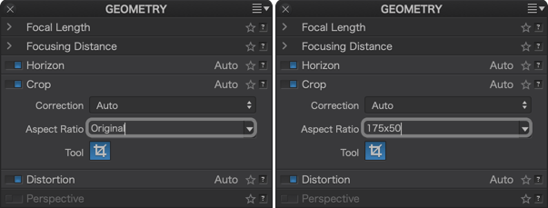
To apply a custom ratio:
- In the Ratio menu in the Crop sub-palette (or as in the toolbar below the image), select Enter a custom ratio.
- Enter 2 values, width and height, separated by x or a / (175×50 or 175/50 in our example) then hit Return.
- The cropping grid adopts the entered ratio, whose values are displayed in the Ratio menu. You can fine-tune the framing and composition of your image so as to be certain that it will be published or printed as desired.
To delete a custom ratio:
- Open the Ratio menu and select Clear Custom Ratios. (Note: All custom ratios will be deleted.)
IMPORTANT
If your custom ratio corresponds to an existing ratio, the values of the latter will be automatically selected and displayed (for example, entered for a 75×50 print = 3×2).
If you enter fancy or inconsistent ratios, DxO PhotoLab will display the limit of accepted ratios.
The values can have a decimal (for example: 22.5×5), with a point (Mac and PC) or a comma (Mac).
There is no limit to the number of custom ratios that you can save.
Distortion
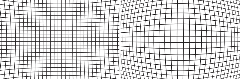
About distortion correction
The geometric distortion introduced by a lens may be in pincushion or barrel form – or sometimes even a mixture of the two. In each case, DxO Labs’ analytical measurements make it possible to correct the distortion such that straight lines in the original scene are correctly reproduced as straight lines in the photo.
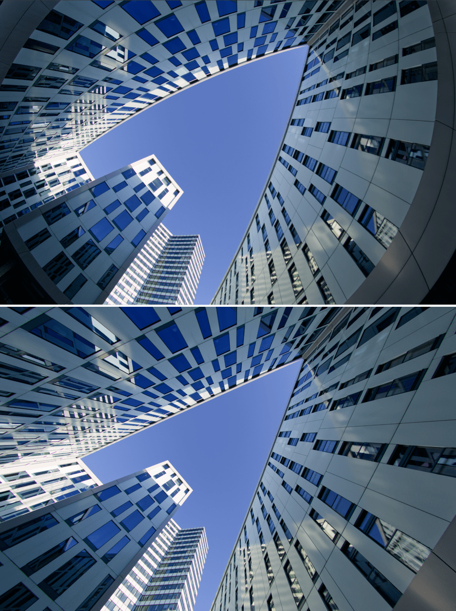
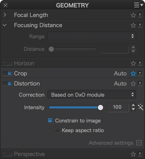
The Correction drop down menu allows you to select either automatic correction based on a DxO Module, or manual correction. Only the manual option will be active if a DxO Module is not available.
The Intensity slider controls the degree of the correction, with a range from 0 to 100%. The default setting is 100%, and you should only depart from this either to avoid the cropping of important details near edges, or for creative reasons.
Automatic distortion correction
Provided the appropriate DxO Module is loaded on your computer for the image you are working on, DxO PhotoLab will automatically correct any distortions.
Manual distortion correction
Select Manual in the drop-down menu if the relevant DxO Module for your camera/lens combination is not available, or not loaded on your computer, or for creative reasons. In any case, first select the type of distortion you want to correct: Barrel, Pincushion, or Fisheye (for fisheye lenses).
Use the grid to help you manually correct distortion.
Changing a fisheye lens into a super-wide-angle lens
You can automatically turn your fisheye shots into ultra-wide-angle-style photos without circular distortion if the camera/fisheye lens combination is supported by a DxO Module. This will be done automatically if the equipment is supported by a DxO optical module, or manually otherwise, by selecting Fisheye in the distortion type dropdown menu, and by refining the adjustment with the Intensity slider.
If you use the Fisheye correction tool, you can uncheck Keep aspect ratio so as to recover a non-negligible quantity of the angle of view.
Constrain to image
Correcting distortion always requires some degree of cropping. By default, DxO PhotoLab displays the cropped image, with the Constrain to image box checked. Uncheck this box if you want to display the whole image including the black areas around the edges that are the result of distortion correction.
Maintaining the aspect ratio
Most of the time, the distortion correction changes the aspect ratio (i.e., the ratio between width and height) of the image. Since the aspect ratio is of great importance, especially if the photo is to be published, it is maintained by default, resulting in some cut-off (cropped) parts along the image edges. If you want to make sure that the entire usable part of the image stays visible, uncheck the Keep aspect ratio box at the bottom of the palette.
Perspective (ELITE edition)
In architecture, the photographer’s position with respect to a building makes it impossible to shoot it face-on. In such cases, the object will look deformed because of divergent lines that are more pronounced the closer they are to the edges of the image.
The Perspective tool lets you correct vertical parallels, horizontal parallels, force a rectangle, and perform an 8-point correction in a completely independent way on each side.
Perspective adjustment could result in significant cropping of your image, so try to avoid pronounced angles when shooting. Do not frame too tightly either, as you risk not having enough space around the subject for perspective adjustment and cropping.
Interface
Located in the Geometry palette, the Perspective tool consists of the following elements:
- Buttons in the top toolbar.
- Perspective Subpalette.
- Lower Toolbar, under the image.
- Control Lines.
- Automatic background cropping.

The buttons on the top toolbar let you activate the different adjustment modes:
- Force parallels (vertical or horizontal).
- Rectangle.
- 8 points.
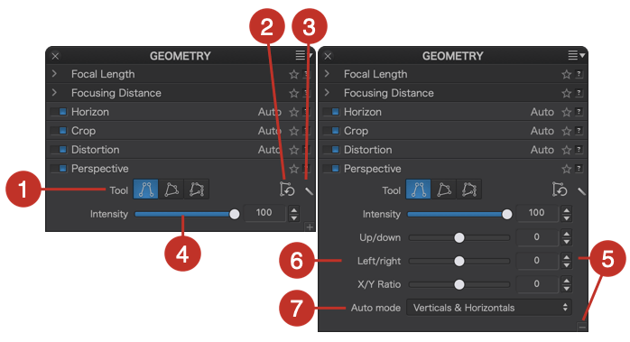
The Perspective subpalette is composed of the following elements:
- The buttons correspond to the different adjustment modes.
- Cancel perspective corrections button.
- The Magic Wand in Auto mode (different Auto modes can be found in the Advanced Settings section).
- The Intensity slider, set to 100 by default, which lets you re-introduce a leaning effect and restores a more natural appearance to your correction as the setting is reduced.
- The advanced settings section is accessed by clicking on “+” (Mac) or on Advanced Settings (PC).
- The up/down, Left/Right and X/Y Ratio sliders turn the image along a horizontal or vertical axis to flatten or stretch the image.
- Choice of automatic, vertical and horizontal, vertical only, and horizontal only adjustment modes.

The lower toolbar has the following functionalities:
- Line color: by clicking on the blue tile (default color), you can change the line color.
- Reset: removes the current perspective correction.
- Apply: applies straightening after placing the lines.
- Close: validates the perspective correction, performs automatic cropping and closes the tool.
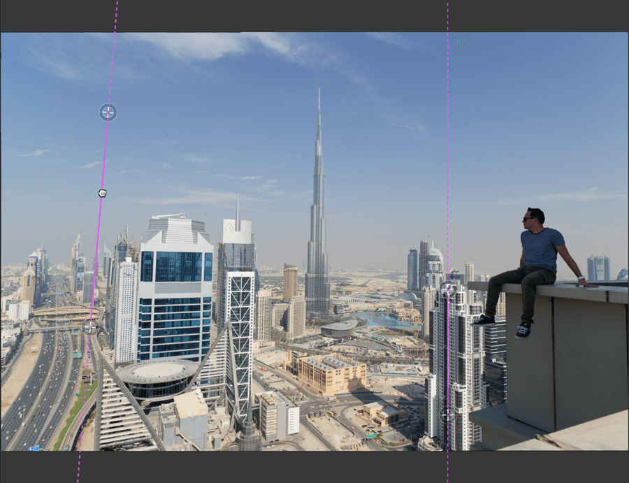
Control Lines
The function of the Perspective tool is based on control lines, two lines in Force parallels mode, 4 connected to each other in Rectangle mode, and 4 without connections in 8 points mode. Each control line is displayed as follows:
- An unbroken blue line (default color and editable in the lower toolbar), that extends as dashes beyond the disks, is the part that you place on a reference line in the image.
- Place the two transparent discs at each end of the unbroken line at the ends of the reference lines in the image.
Control lines can be moved with the mouse:
- Move the whole image by grabbing the unbroken line (the pointer becomes a Hand tool).
- Turn and rotate in all directions by grabbing a disc.
- Change the length by moving the disk along the line axis.
- In Rectangle mode, the lines are bound to each other by the disks, so each time you move a disk you affect both lines at once, one vertical, and one horizontal.
- In 8-point mode, the 4 lines are completely independent and free to move around.
- If you position or modify a control line while holding down the Cmd key (Mac) or Ctrl key (PC), the correction will be instantaneous.
You can draw a new line using the “+” pointer that appears as the mouse passes over the image.
Background cropping
Adjusting the perspective and modifying the geometry of the image in general leads to distortion which is more or less noticeable according to the amount of correction applied, but will inevitably involve some cropping. Background cropping, that is the portion of the image that will disappear on cropping is indicated by the black areas around the image.
When you confirm the correction with the Close button, the image will automatically be reframed as tightly as possible, keeping the maximum amount of the image, after cropping has been into account. Of course, you can reframe afterwards using the Crop tool (Geometry palette).
Fixing perspective
Auto mode
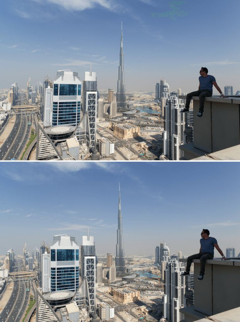
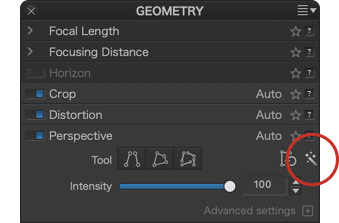
If your image has enough horizontal and/or vertical reference elements, you can use automatic mode, which you can manually redo if you wish.
Here is how to use it:
- In the Geometry palette, Advanced Settings, Auto Mode menu, select one of the 3 modes on offer, the default mode takes into account both verticals and horizontals.
- Click on the magic wand.
- Here, no confirmation is required. Once the correction has been completed, you can switch to another image or another tool.
Forcing parallels
This mode lets you correct simple scenes like a building with an obvious shifting of vertical or horizontal lines:
- Go to the Perspective subpalette and click the Force Parallels button.
- Two vertical lines appear as overlays on your image.
- Position them on two vertical or horizontal elements in your image, preferably in the same plane.
- Adjust the position, size and inclination of the control lines.
- Click Apply to see the result.
- If the correction gives the impression that the building gets wider at the top, you can restore a natural aspect by reducing the adjustment of the Intensity slider (75 is a good compromise).
- Click Close to approve (image is automatically cropped).
Forcing a Rectangle
With this mode, where 4 lines are connected to each other, you can easily add a subject such as a painting, window, door, or any frame that you were unable to perfectly align to and whose different parts are on the same plane:
- Go to the Perspective subpalette and click the Rectangle button.
- 4 connected lines appear overlaid on your image.
- Position the disks at each corner of the subject and adjust the position and inclination of the lines using the reference lines from the image.
- Click Apply to see the result.
- Click Close to approve (image is automatically cropped).
8 points
This mode works like the rectangle mode, but all 4 lines are independent which lets you place them where you want in the image, this is useful if the reference lines are located on different planes and at different distances:
- Go to the Perspective subpalette and click the 8 points button.
- 4 independent lines appear overlaid on your image.
- Position the lines over the reference lines in the image, adjust their slant and length.
- Click Apply to see the result.
- Click Close to approve (image is automatically cropped).
Advanced adjustment sliders
When you make perspective adjustments and depending on the image and care that was taken with the shot, results can sometimes cause problems with orientation, geometric deformation and, quite simply, the natural look of the image. The following three sliders let you compensate for these problems, but keep in mind that they are intended as subtle adjustments:
- The up/down slider rotates the image around a horizontal axis passing through the center of the photo. So the image will swing towards or away from you, like a playing card falling on its face or its back.
- The left/right slider rotates the image around a vertical axis passing through the center of the photo. Moving to the left, the left edge of the image moves closer to you, and the right edge spins away (and vice versa).
- The X/Y ratio slider, going to the left, crushes image vertically and reframes it to the left and right. Moving right, the slider will stretch the image vertically and reframe it top and bottom.
The Local Adjustments palette
DxO PhotoLab local adjustment technology takes your photo editing to the next level by letting you target specific parts of the image, either to highlight a detail or to perform precise touch-ups. Whether it’s to brighten the sky, bring out a backlit subject, or enhance the colors or sharpness of a specific detail, the possibilities are endless.
Accessing local adjustments
To access Local Adjustments, simply go to the palette and click on one of the buttons to activate the desired tool. The palette also contains mask options as well as the full set of correction tools that can be used locally.
The buttons are (from left to right):
- Control Point
- Control Line
- Graduated Filter
- Luminosity Mask (if DxO FilmPack is installed and activated)
- Hue Mask
- Auto Mask
- Brush
- Eraser
The palette also contains the following sections:
- Mask list and commands
- Mask options
- Exposure*
- Selective Tone*
- DxO ClearView Plus*
- Contrast*
- White Balance*
- HSL*
- Sharpness*
- Blur*
* You can find the description of these tools in the paragraphs dedicated to the different palettes in the Customize tab. Click on the items in the list to access them.
Expand/Collapse
If you place the mouse anywhere in the Local Adjustments palette and right-click, a menu will allow you to perform the following actions:
- Expand all: all palettes and sub-palettes of tools available in Local Adjustments are displayed in their entirety so that you can make your corrections.
- Collapse all: all palettes and sub-palettes of tools available in Local Adjustments are closed.
Managing the masks
The Local adjustments palette lets you manage and view your local masks and corrections, either together or individually, and also to alter their overall appearance with an opacity setting or mask inversion.
Each time you create Local adjustment masks by using the brush, graduated filter, automatic mask, luminosity mask or control points/lines, the masks will appear in the palette as part of a list. Regardless of the order, the resulting image is the same.
When you move the mouse over the mask list, the line you’re hovering over lights up, and you will see the mask by itself in the image, whether it is active or not, as the other masks are temporarily hidden. This way you can check which mask in the list corresponds to that used in your image, and which mask to concentrate on for fine-tuning.
Opacity slider
After you make your local adjustments, you can fine-tune the intensity and effect of the corrections with the Opacity slider, which is set to 100 by default. This way, if you find your corrections are a bit too strong, you don’t have to fumble around in the palette to figure out which setting(s) to change or reduce, or (worse) start again from scratch.
The Opacity slider shows up automatically in the palette by using any of the local adjustment tools.
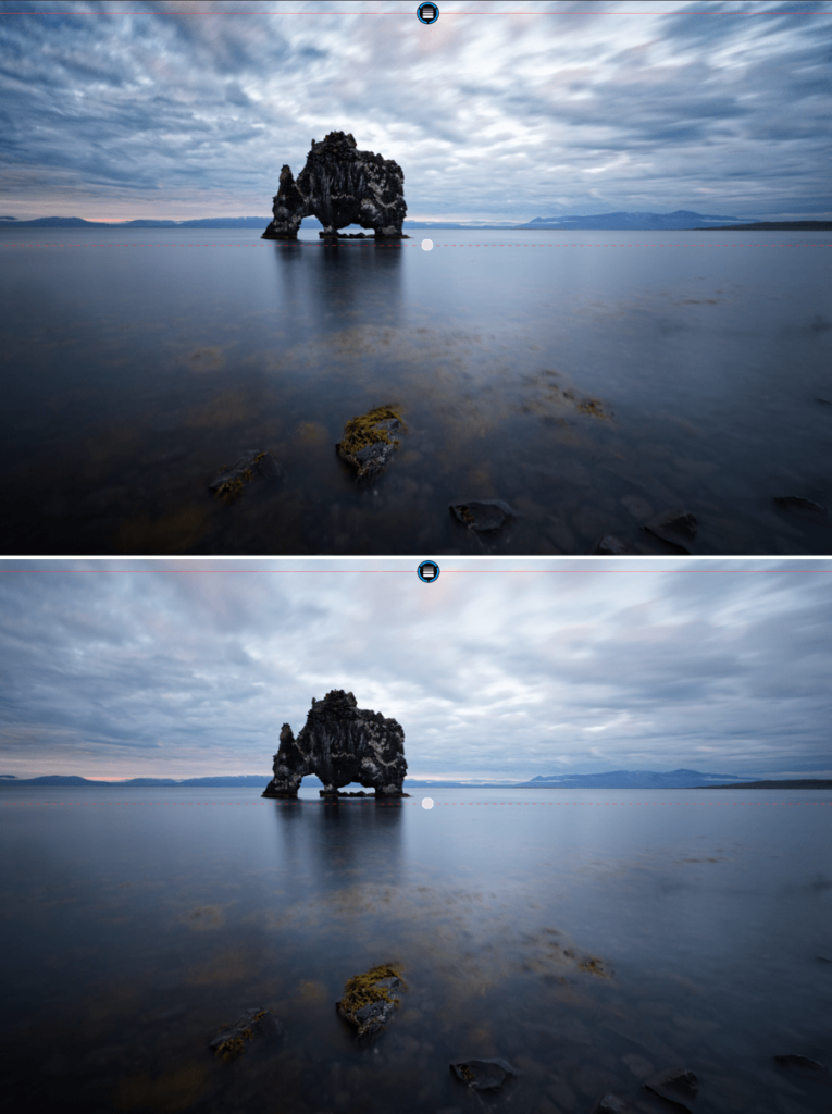
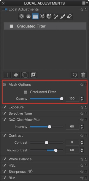
Mask selectivity sliders
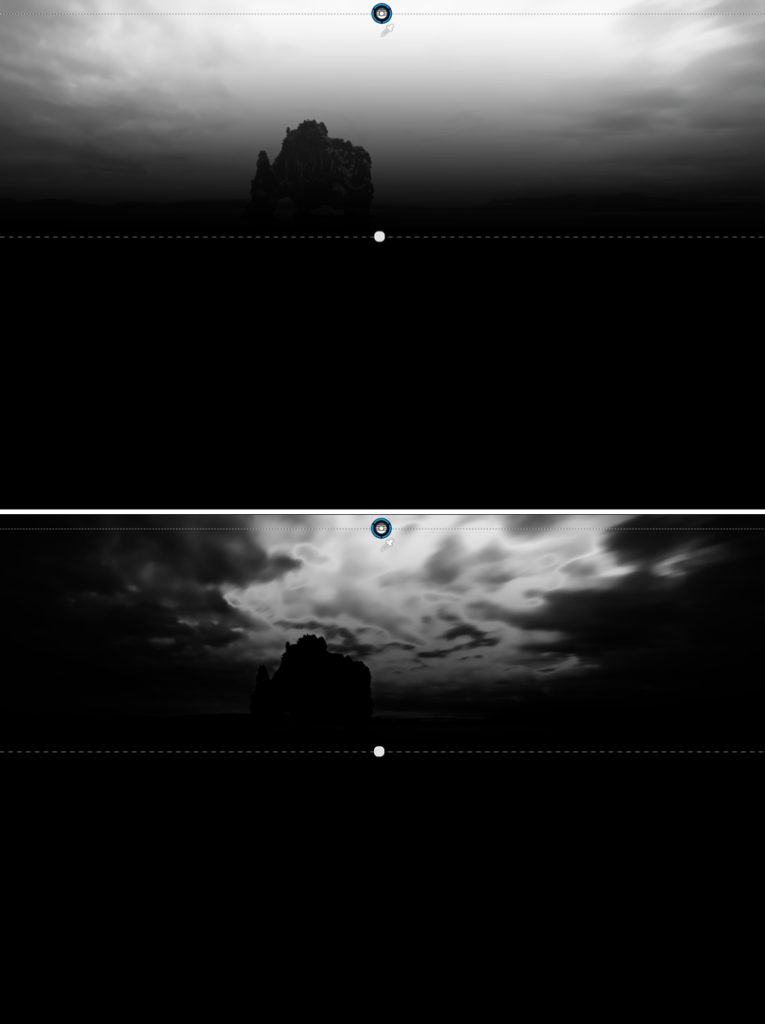
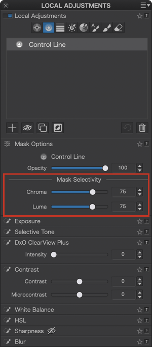
You can use the Mask Selectivity sliders with Control Points or Control Lines, which allow you to adjust the tolerance range of the color that a Control Point or Control Line covers. This will allow you to include variations of hue and brightness level in your correction (such as in order to take into account variations in skin tones; see example below).
- Chroma: defines the range of color variation (default setting 50%).
- Luma: defines the brightness range for the color (default setting to 50%).
Show/Hide mask
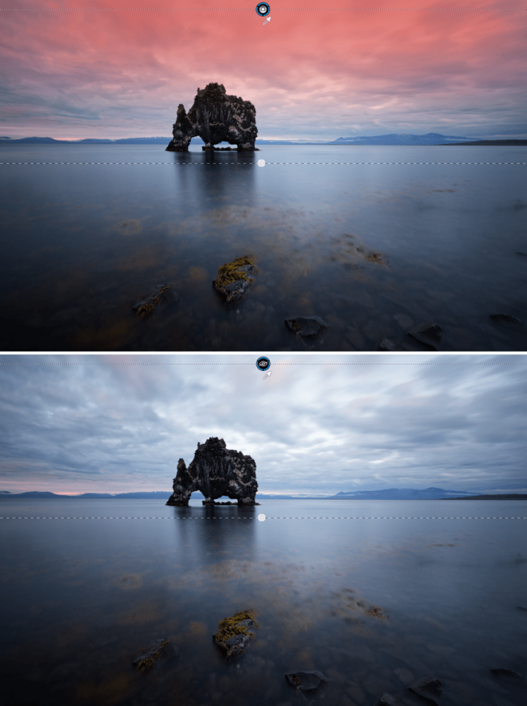
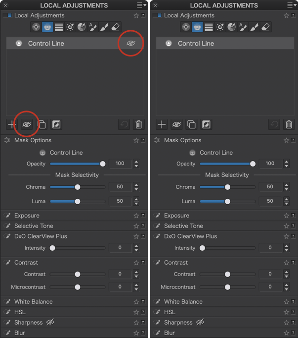
You can enable/disable the display of the color mask and/or associated corrections in the following ways:
- Temporarily enable/disable the color mask display of an active mask: hover the mouse over the mask disk (in the image) or over the mask name in the Local Settings palette. You can also place the mouse over the image (the color mask is displayed) or move it away (the color mask is not displayed). Finally, you can also check or uncheck Show mask in the toolbar below the image.
- Enable/disable the display of the color mask and the corrections applied to the active mask: in the list of masks in the Local Adjustments palette, place the mouse to the right of the name of the active mask and click on the crossed-out eye. You can also click on the button with the eye at the bottom of the palette. Until you reactivate the display by clicking on the crossed-out eye, the color mask and the corrections of the active mask will not be displayed, even when you move the mouse over the image or the disk (the latter also displaying as a crossed-out eye).
- Temporarily disable the display of all local adjustment masks and associated corrections: click on the switch in the Local Adjustments palette (and click again to re-enable their display).
The display mask color by default has changed to red, and you can customize it. However, the user guide screenshots show the previous default color (cyan).
Inverting the mask
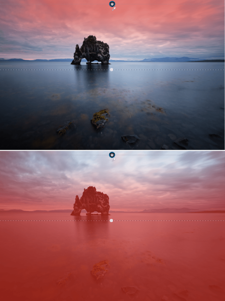
The Invert mask button lets you invert a local adjustment and the rest of the image with just a single click. For example, if you make an area darker with the Brush, by clicking on Invert mask the area will return to its original brightness, and the rest of the image will become darker. Another example: if you draw a graduated filter from the top of the image to the bottom, and click Reverse Mask, the graduated filter will be applied from the bottom of the image upwards.
Renaming a mask
By default, the masks in the list of the Local adjustments palette are named after the tool used. You can rename a mask whatever you like to help recall, at a glance, what type of correction it is and/or where in the image you have used it, in relation to your workflow for example, etc.
Simply click on the mask name in the list, and enter the new name. There is no need to confirm using the Enter key. To change another name, simply go to the next mask in the list.
On a PC, you can right-click and select Rename from the context menu (you can also press the F2 key).
Changing the name does not change the order of the masks in the list.
Duplicating a mask
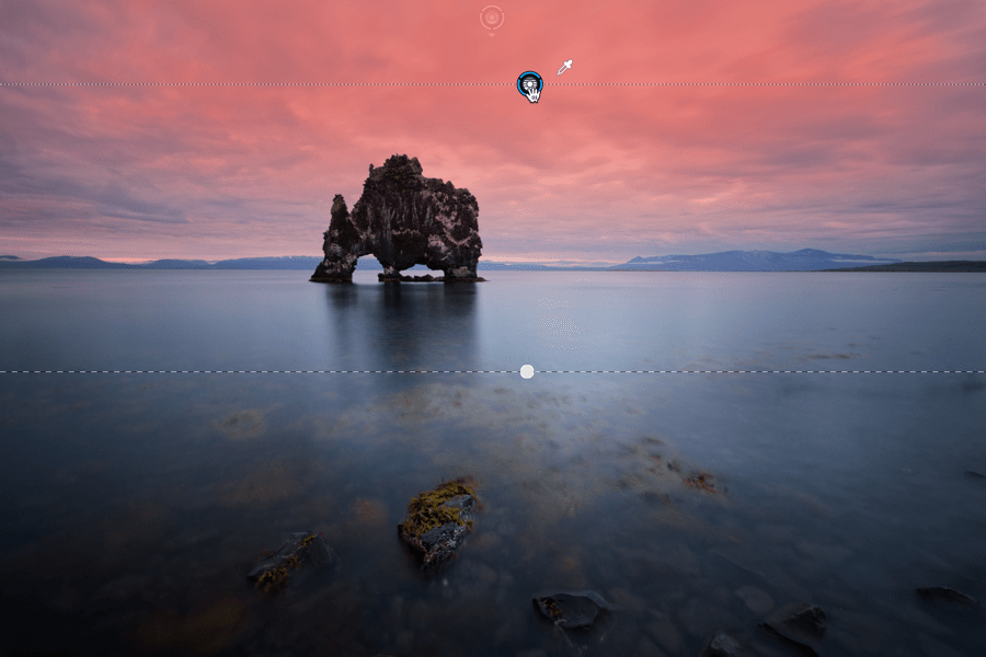
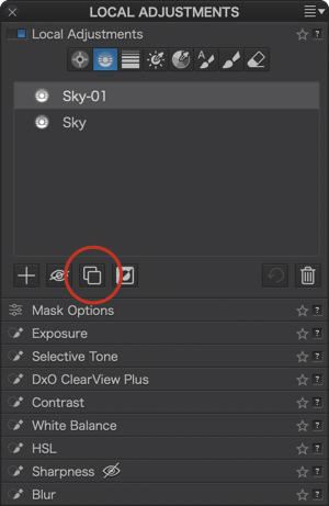
Duplicating a mask is a quick way to add a mask that uses the same corrections. There are two ways to do this:
- Click on a mask in the list of masks in the Local Adjustments sub-palette, right-click, and then select Duplicate mask from the context menu.
- Click on a mask in the list, then click on the Duplicate mask button in the bottom right of the sub-palette.
The duplicated mask will be superimposed on the original mask; to move it, click on the disk and drag it with the mouse. You can duplicate a mask as many times as you like; PhotoLab keeps the name of the original mask (which you can change if you wish).
Deleting a mask
To remove a mask from the list, select it by clicking on it in the list, then click on the Remove Mask button in the bottom right corner of the sub-palette. You can also do this via the right-click context menu.
To delete a mask in the image, activate its disk by clicking on it, then press the Delete (PC and Mac) or Backspace (Mac) key.
Using masks
A local adjustment is simply a retouch or correction that you apply to a specific area or element in the image. The retouching is applied on top of any general corrections, which you do using the preset option or the manual and automatic correction tools in the Customize tab.
When you use one of the local adjustments tool, you create a mask over the part of the image you want to retouch, and then you use the different sections in the palette to make adjustments to the mask. You can choose to highlight the retouched areas with a blue mask, which makes it easier to see the parts of the image that will be adjusted.
Common interface features
After you select a mask, the interface will display the following common features:
- The mask represented by a disk containing the icon of the selected tool. The active mask disk is black with a blue border, while any inactive masks are grayed out.
- A floating help window in the bottom right-hand corner that displays a list of possible actions and keyboard shortcuts. This window is shown by default, and can be closed by clicking the X button in the top left corner.
Mask display options (PC)
When the Local Adjustments are active, and if you hover with the mouse, the 2 following options will show up in the top right corner of the image:
- Show cropped areas: Displays the entirety of a cropped image.
- Show masks: Toggles the display of the color or black and white display masks.
- Color overlay/ Black & White: Lets you select the overlay mode, color or black and white when clicking the arrow. Clicking on the square will open a system dialog box, where you can choose a different color for your masks, to help to better visualize your masks against the image background.
Toolbar and mask display options (Mac)
When you activate the local adjustments, a toolbar below the image displays a number of options, depending on the tool selected:
- Show brush/auto mask/eraser settings: displays a floating window with the brush settings at the bottom left of the image.
- Add a control point/control line: lets you add control points or control lines to the active mask.
- Protect area: Adds a control point or control line to prevent you correcting another point or control line.
- Show cropped areas: Displays the entirety of a cropped image.
- Show Masks: Toggles the display of the color or the black and white display masks. Black means that the mask and the associated corrections have no effect on the image, white means that the mask and the corrections apply fully, and shades of gray indicate where, more or less, the mask and the corrections have an effect.
- Mask Color: Lets you change the default color (red) of the masks. Clicking on the square will open a system dialog box, where you can choose a different color, to help to better visualize your masks against the image background.
- Reset: Removes all local adjustments made to the image.
- Close: Exits local adjustments.
Show cropped areas
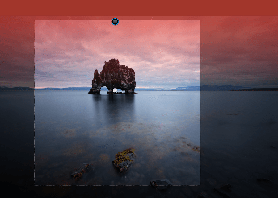
The uncropped display option lets you show the totality of a cropped image, and to position masks (brushes, control points, graduated filters, etc. or to take control line samples from outside the frame. To enable it:
- Mac: Check the option Show Cropped Areas in the local settings toolbar under the image.
- PC: Check the Show Cropped Areas option in the upper right floating box (place the mouse over the image to make it appear).
The out-of-frame areas are indicated by a dark translucent mask.
Comparing the image with and without local adjustments
The Reference Image tool in DxO PhotoLab lets you judge your photo with and without local adjustments. This will show you the impact of the local adjustments on your image and help you decide whether you want to make further adjustments.
To see the image with and without local adjustments:
- Local Adjustments must be active.
- In the top toolbar, click the arrow next to the Compare button and then select All corrections except Local Adjustments from the menu.
- Clicking and releasing the Compare button in the top toolbar will alternate the viewer between displaying the image with and without local adjustments.
To deactivate the comparison, go back to the Compare menu and uncheck All Corrections Except Local Adjustments.
Local Adjustments tools
The local adjustment tools are presented in the order of the buttons in the palette.
Control Point
Control point technology is now available in DxO PhotoLab.
This is a local adjustment tool with a special function: when the user clicks on the image to set a control point, the tool will take brightness, contrast and color characteristics of the pixels where the control point is placed into account, in order to apply the correction across pixels with the same characteristics within a user-defined radius.
For example, if you place a control point on a bright red mug with a contrasting background and adjust the area so that it includes the mug, the corrections will only be applied to the mug, and not to the background.
If the image contains another red object and you don’t include it in the defined area, the second object will remain unchanged. However, if you include it within the defined area, it will be affected by the same changes that are applied to the red mug. If you apply another control point mask to the object, any adjustments you make will not affect the first control point mask.
When to use control points
Control points let you make selective adjustments to areas defined by the control point’s radius of action, without affecting portions of the image that are either outside the radius of action or within the radius of action but concerning pixels with different characteristics from those covered by the control point.
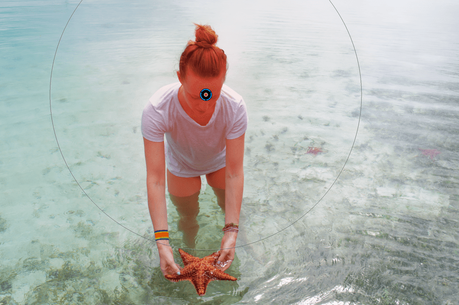
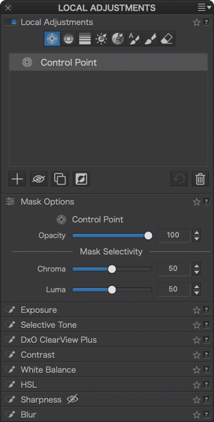
You can also use Control points and Control lines in the same mask.
This also applies to Protection Control points and lines.
Activating Control points
As with the other local adjustment tools, go to the Local Adjustments palette, and click on the Control Point button.
If you are already working with local adjustment tools, right-click in the image to display the radial menu, then select Control Point. You can apply as many control point masks as you want. You can also use them in an image that already has other types of local adjustment masks.
Once you have activated local adjustments, you can switch from one of the other tools to Control Points using the keyboard shortcut Shift+C.
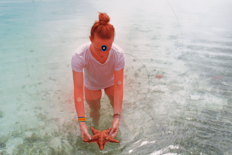
Using Control points
After you activate a control point mask, the mouse pointer changes to crosshairs when you roll over the image. Click inside an area or on a part of the image that you want to correct. The control point mask is represented by a disk with a plus sign in the middle and a larger surrounding circle. As with the other tools, the blue border indicates an active mask.
Control points can be interconnected, allowing you to apply the same correction to several places in the image. To do this with the active mask, click on the image as many times as you want. Secondary control points are represented by a simple crosshair icon and a circle indicating the area where changes will be applied (you can adjust the size for each secondary control point separately). Apply the desired adjustment using the Equalizer. The effect will be applied to all control point masks belonging to the same mask — that is, to the first control point and to all its secondary control points.
Note that you will need to create a new control point mask each time you want to apply a different adjustment.
Adjust the area covered by the control points by clicking on the outside circle with the mouse and then using the Equalizer to apply the settings you want.
Moving control points
Click on the central disk to drag a control point to wherever you want.
Displaying the mask in grayscale
To better visualize the corrections and settings made with the active control point, you can activate a grayscale mask by hitting M (PC) or Shift+M (Mac).
Once you’ve activated the mask, the content of the active control point is displayed in monochrome. The areas and elements most affected by the correction are white, the unaffected areas are black and the variations in gray indicate the areas more or less affected. This lets you see and control the applied control point corrections with much greater precision.
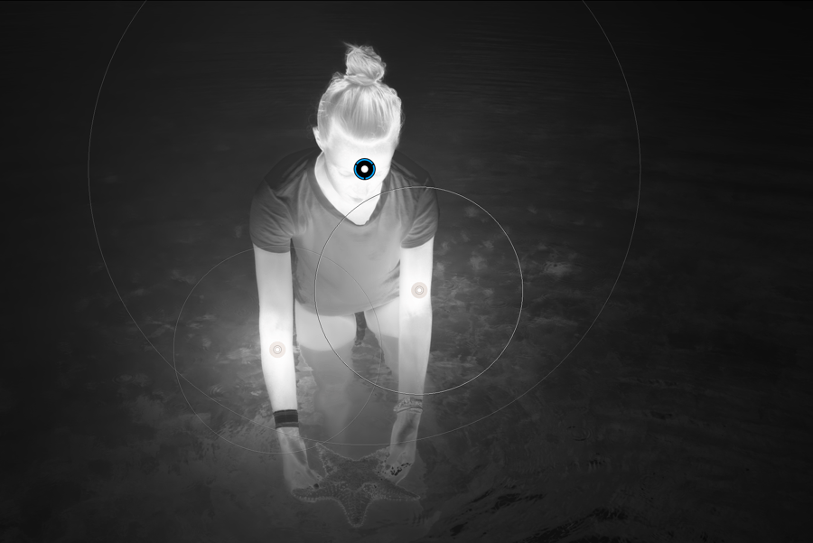
Protecting part of an image
You can apply a protective Control Point, which prevents another Control Point from applying its correction to a portion of the image. Press the Alt (PC) or Option (Mac) key, then click to place the protective Control Point where you want it (on Mac, in the toolbar below the image, you can also click on the Control Point icon with the “–” (minus) sign). Make your corrections with the Equalizer: they will not be applied to the protected area.
You can also combine one or more protective Control points with a Control line.
Control Line
Control Lines use the same principles as Control Points, and to some extent, the same principles as the Graduated Filter, with the advantage of covering the entire width of the image. Pixel analysis is not done with a Control Point, but with an eyedropper that you move around the mask to select the portions of the image to be corrected.
A good example is correcting a blue sky with clouds. If you are using Control Points, you will need to place several of them and make sure they overlap and are grouped together to ensure a consistent correction. With the Control Line, you simply draw it over the entire sky and then, with the reference dropper, click on the blue sky so that the correction is applied evenly to that portion of the image.
Activating a Control line
As with the other local adjustment tools, go to the Local Adjustments palette, and click on the Control Line button.
If you are working with local adjustments, right-click on the image to display the radial menu, then select Control Line. You can apply as many Control Lines as you like, and combine them with other local adjustment masks, except for the Eraser.
Using Control lines
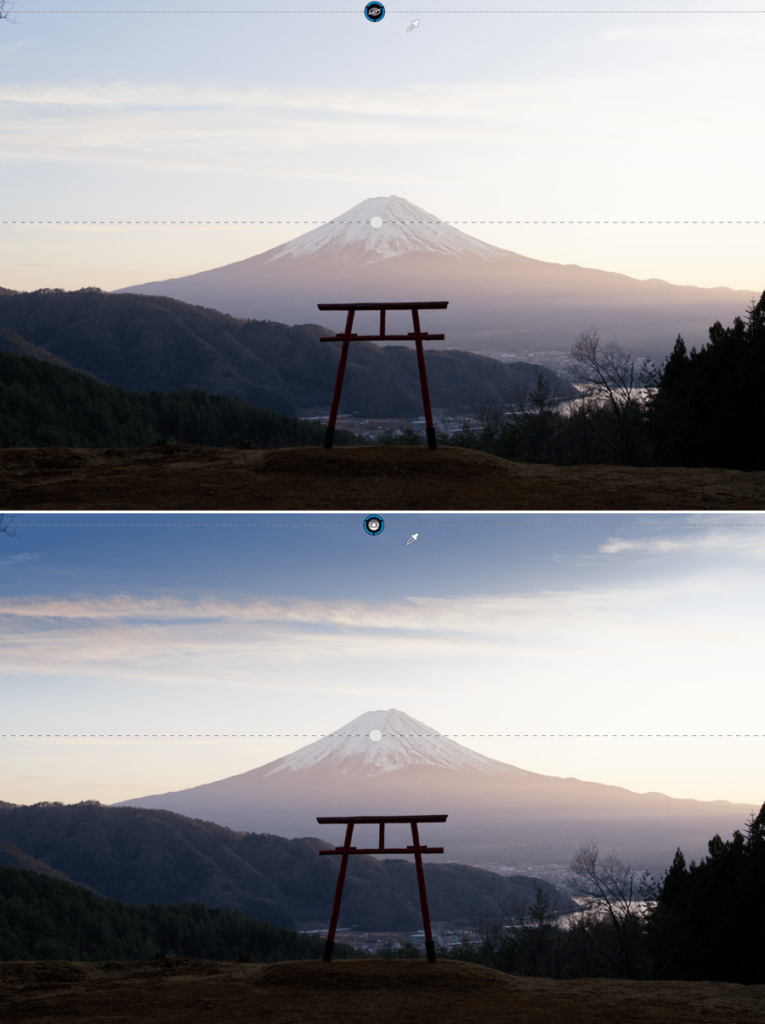
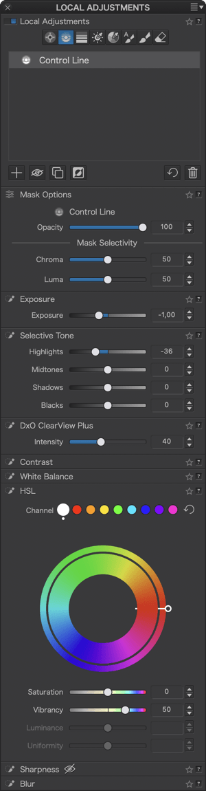
After activating the Control line in the radial menu, go to the image. The mouse pointer changes to a “+”, and all you have to do is draw the Control line so that it covers the portion of the image to be corrected. The Control line is located between two dashed lines. The bottom line can be tilted or moved to increase or decrease the size of the area to be corrected.
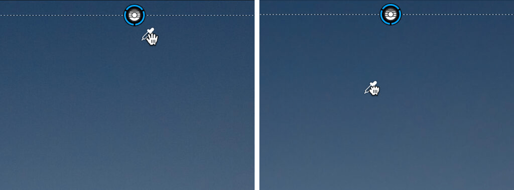
Select the reference area using the eyedropper near the disk: grab it with the mouse and drag it to wherever you want in the image. Then all you need do is make your corrections with the available tools.
Moving the Control Line
You can move a Control line by grabbing its disk. You can move the eyedropper at the same time, even if you have positioned it somewhere else, by pressing the Ctrl (PC) or Cmd (Mac) key.
Displaying the gray mask
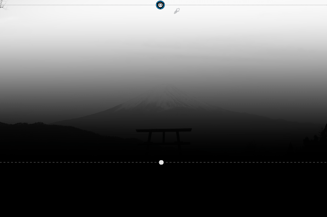
To better visualize the corrections and adjustments made with the active Control Line, use a grayscale mask, activated with the M (PC) or Shift+M (Mac) keys, or by checking Show mask, below the image.
The white areas indicate the maximum level of correction, the uncorrected areas are black, and the gray variations indicate the various intensities of the corrections. This allows you to see the reference areas and corrections applied using the Control Lines with greater precision.
Protecting part of an image
Just like with Control points, you can apply a protective Control line that prevents another Control line from applying a correction to a location in your image. Press the Alt (PC) or Option (Mac) key, then click to place the protective Control Line where you want it (on Mac, in the toolbar below the image, you can also click on the Control Line icon with the “–” (minus) sign)., then draw the line in the image and use the eyedropper to sample the reference area to be protected. Then make your corrections using the Equalizer, they will not be applied to the protected area.
You can also combine one or more protective Control points with a Control line.
Graduated Filter
When to use the Graduated Filter
The graduated filter simulates the effect of an optical graduated filter fitted to a lens. They are especially useful for balancing the exposure of landscape photos and reducing the extreme contrast between a brightly lit sky and dark ground.
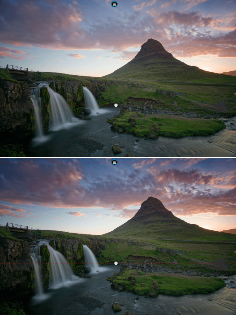
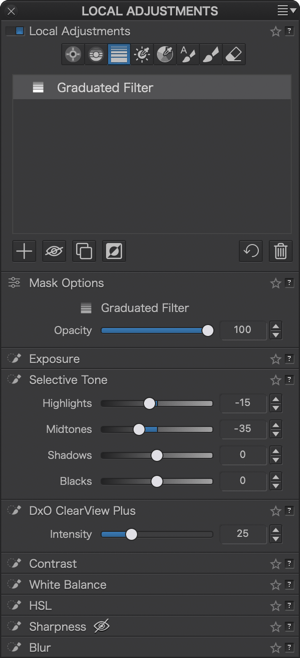
Activating the Graduated Filter
As with the other local adjustment tools, go to the Local Adjustments palette, and click on the Graduated Filter button.
When local adjustments are enabled, you can switch from any of the other tools to the graduated filter using the Shift+G keyboard shortcut.
Applying the Graduated Filter
Once you’ve activated the graduated filter, the mouse pointer changes to a cross (Mac) or to a gradient icon (PC). Position it at the top of the image, then move the mouse down.
The graduated filter includes the following elements:
- A solid line, with the mask disk at the starting point of the graduated filter.
- A dashed line with a round point indicating the center of the mask, which you can use to rotate the filter.
- A transparent mask with a blue gradient indicates how the mask is applied with its gradient. The effect starts off at its most intense then gradually fades toward the dotted line.
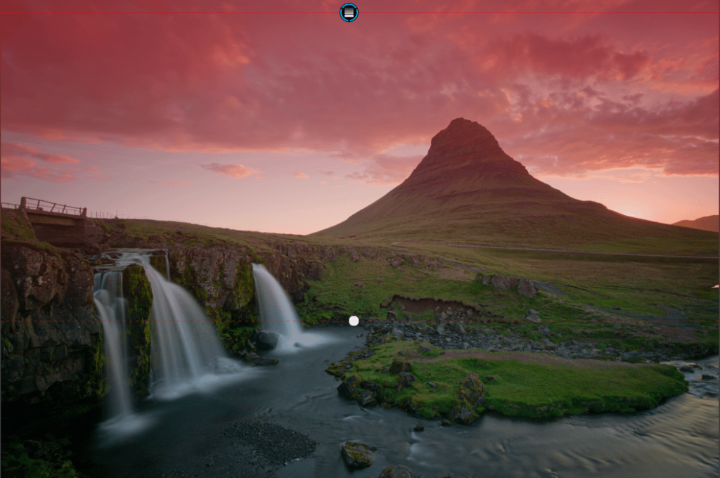
To apply corrections, use the tools in the palette. You can layer several graduated filters in the same area with a new adjustment each time, or simply combine several corrections in the same graduated filter.
Managing the Graduated Filter
- You can move the graduated filter anywhere in the image.
- You can even tilt it by clicking on the round point on the dashed line.
- You can move the dashed line in two directions to either extend or reduce the area of strongest effect.
- You can also move the starting line in either direction to adjust the area of the graduated effect.
- You can apply the graduated filter from any direction—starting from the top, the bottom, sides, or corners.
- Of course, you can create several graduated filters in the image.
- To rotate the Graduated Filter, grab the dotted line with your mouse and rotate it. You can rotate the filter through 360°. The PC version lets you rotate in increments of 90°, 180°, 270°, and also from 0° to 360° by pressing the Ctrl key.
- You can apply several graduated filters to the image. If you move or edit a graduated filter mask, the corrections are shown in real time.
- If you want to delete a graduated filter, activate it by clicking on the mask disk, then press the Backspace key (Mac) or the Delete key (PC).
Add or subtract from the graduated filter
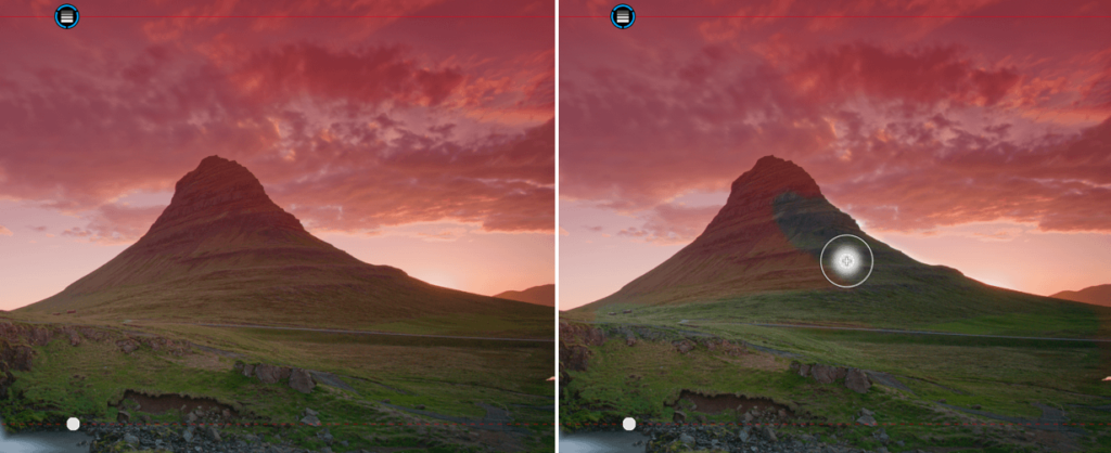
When applying a graduated filter to an image, e.g. to darken or enhance the sky, you will not want the effect to apply in equal measure to all other elements, such as buildings, landscapes, statues, etc. below it, and this is where the Eraser can help you to subtract from the selection. On the other hand, you may want to add certain elements of the image to the graduated filter, because it does not cover them. In this case, you can use the Brush tool to add to the selection.
- Add to the selection: with a Graduated Filter active, go to the Local Adjustments palette, click on the Brush button and paint in the image to extend the selection.
- Subtract from the selection: with a Graduated Filter active, go to the Local Adjustments palette, click on the Eraser button and paint in the image to remove parts from the selection.
Luminosity Mask (DxO FilmPack installed)
The Luminosity Mask is only available with DxO FilmPack installed and activated.
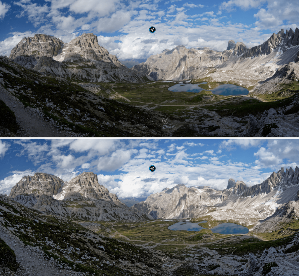
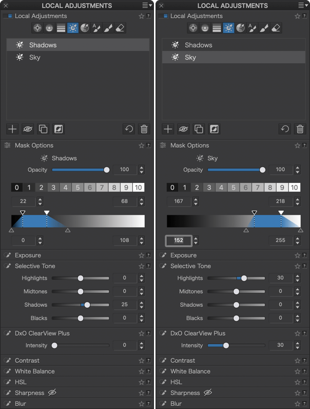
The Luminosity Mask allows you to correct an image based on a range of brightness that you can adjust with very high precision, including at the transition level.
When you activate the Luminosity Mask, open the Mask Options sub-palette to access the tools.
Selecting the luminosity range
To select the luminosity range, you have the following tools:
- Eyedropper: replaces the mouse pointer and activates the tool, making it the first mandatory step to use the Luminosity Mask. Click on the image, the round point is positioned and the trapezoid indicates the selected luminosity range. You can click and repeat the sampling as many times as you want. You can move the round point everywhere in the image to change the sampling area and the relevant luminosity range (in that case, the trapezoid updates accordingly).
- 11 luminosity zones: the scale from 0 to 10 also allows you to select a brightness range easily, by clicking on one of the tiles, from the darkest (0) to the brightest (10), the middle values being at 5.
- Trapezoid: in addition to its role of indicating the selected brightness range, you can adjust it by moving the trapezoid in the scale.
In the picture, the Luminosity Mask is shown by a color mask and a disk, as every Local Adjustments tool.
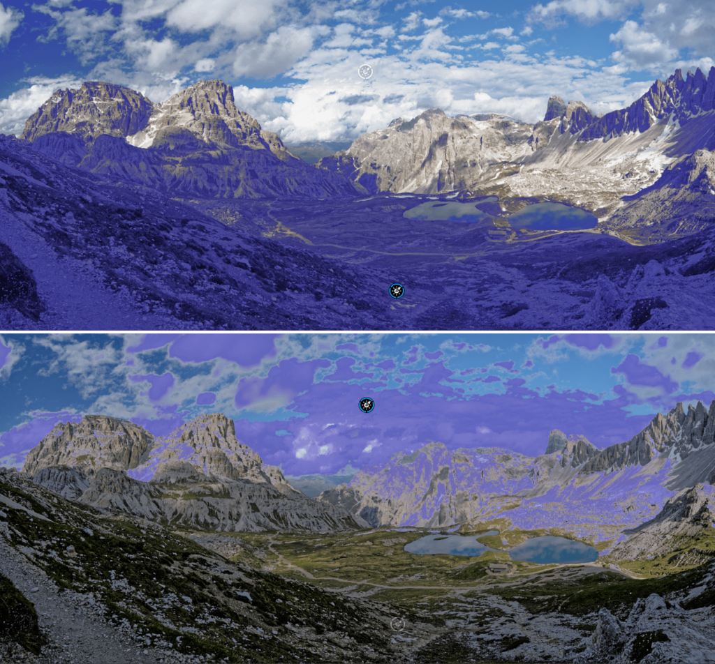
Refining the Luminosity Mask
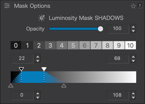
No matter which method is used to determine the luminosity range, you can refine it using the following tools:
- The black and white triangles above the trapezoid, as well as the associated dotted lines, represent the lower (dark tones) and upper (light tones) limits of the selected luminosity range. The corresponding levels values – from 0 to 255 – are indicated in the two upper level value fields. You can also adjust the values by clicking on the arrows or by direct typing.
- The triangles below the trapezoid indicate the limits in the transition of luminosity levels (fall-off), between the selected range and the rest of the image. The further you move these triangles from the dotted lines, the more you extend the fall-off, the more you dilute the luminosity levels, and the closer you move the triangles, the more you reduce the transition levels and the more abrupt the fall-off will be. You can also use the two lower value fields to adjust the levels, from 0 to 255.
Thus, by acting on the position and extent of the trapezoid, as well as the extent of the fall-off, you will arrive at an extremely precise selection of the range to be corrected. In addition, the Opacity slider, set to 100 by default, allows you to reduce the intensity of the Luminosity Mask and the local adjustments associated with it.
If you move the Luminosity mask disk in the picture, the mask, the trapezoid and the values will be updated accordingly.
If you move the trapezoid, the disk in the picture will be repositionned to match the values.
Add to or subtract from the Luminosity Mask
You can go even further in the precision of the Luminosity Mask by adding to the selection with the Brush, or by subtracting from the selection with the Eraser:
- Add to the selection: with a Luminosity Mask active, go to the Local Adjustments palette, click on the Brush button and paint in the image to extend the Luminosity Mask.
- Subtract from the selection: with a Luminosity Mask active, go to the Local Adjustments palette, click on the Eraser button and paint in the image to remove parts of the Luminosity Mask.
The Hue Mask tool
The Hue Mask tool allows you to correct an image based on a color range that you can adjust with great precision, including transitions.
Description of the Hue Mask Sub-palette
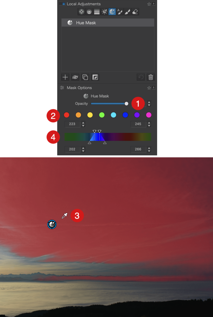
Available in local adjustments, the Hue Mask sub-palette consists of the following elements:
- Opacity: The slider allows you to adjust and refine the intensity of the hue mask and the associated settings. By default, it is set to the maximum value of 100; moving it to the left will gradually reduce the correction. You can also enter a value or adjust it using the up/down arrows.
- Hue Channels: There are eight predefined channels available for an initial selection of a range of hues, which can then be refined using the trapezoid:
- Red
- Orange
- Yellow
- Green
- Cyan
- Blue
- Violet
- Magenta
When you click on one of the channels, the trapezoid displays the corresponding range of hues, and in the image, you will see the associated indicator and the overlay mask display if the “Show Masks” option (toolbar under the image) is checked.
- Hue Selection eyedropper: When the Hue Mask tool is activated, the mouse pointer turns into an eyedropper when hovering over the image. Click on the image to select a range of hues; you can click and resample as many times as you like. After selecting the range of hues, it is represented in the trapezoid and in the image by an indicator and a color display mask, if the “Show Masks” option (toolbar under the image) is checked.
- Trapezoid: In addition to indicating the selected range of hues, you can adjust it by moving it along the scale. Regardless of the method used to determine the range of hues, you can refine it using the following tools:
- The black triangles above the trapezoid, along with the associated dotted lines, represent the boundaries of the selected hue range. The hue values—ranging from 0 to 360*—are shown in the top fields. You can also adjust the values by clicking the arrows or by direct input.
- The gray triangles below the trapezoid indicate the hue transitions at each end of the selected range. Moving these triangles away from the dotted lines widens the transitions and dilutes the hues. Moving them closer to the dotted lines narrows the transitions, making them more abrupt. You can also use the lower value fields to set chromatic values from 0 to 360.
- If the hue range you have selected is located at each end, you can move the color scale for more convenience.
By adjusting the position and extent of the trapezoid, as well as the extent of the transitions, you can achieve an extremely precise selection of the hue range to correct using the local adjustment sliders. This allows you to lighten, darken, saturate, etc., the portion of the image corresponding to the hue range represented by the trapezoid.
- *The values from 0 to 360 simply represent the color wheel, a circular representation of primary colors and their complementary colors. You can find the same representation in the HSL tool in DxO PhotoLab.
- **If you move the Hue Mask disk within the image, the mask, trapezoid, and values will be updated accordingly.
- ***If you move the trapezoid, the disk shown on the image will be repositioned to correspond to the hue range.
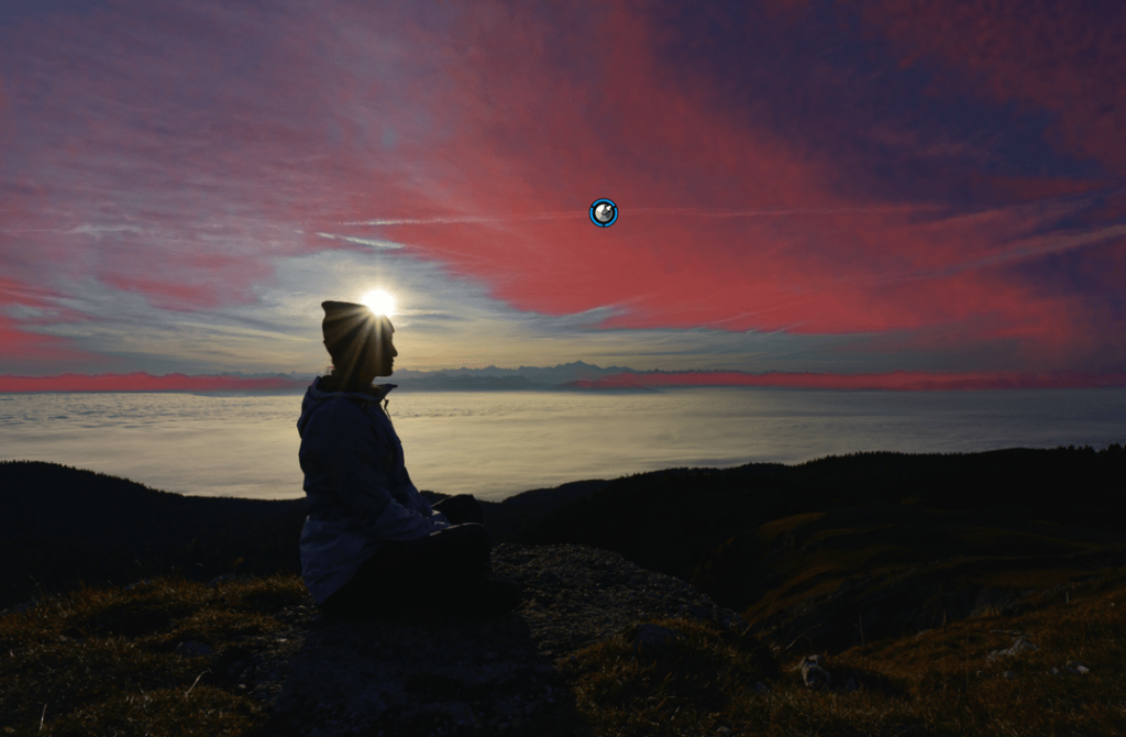
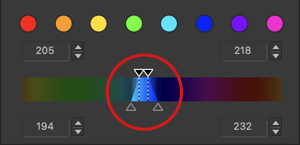
The trapezoid after selecting a hue range (blue)
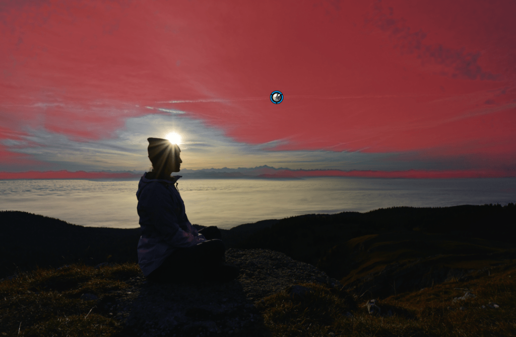
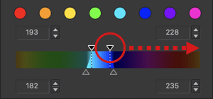
Extending the range of hues

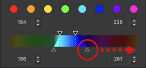
Extending transitions
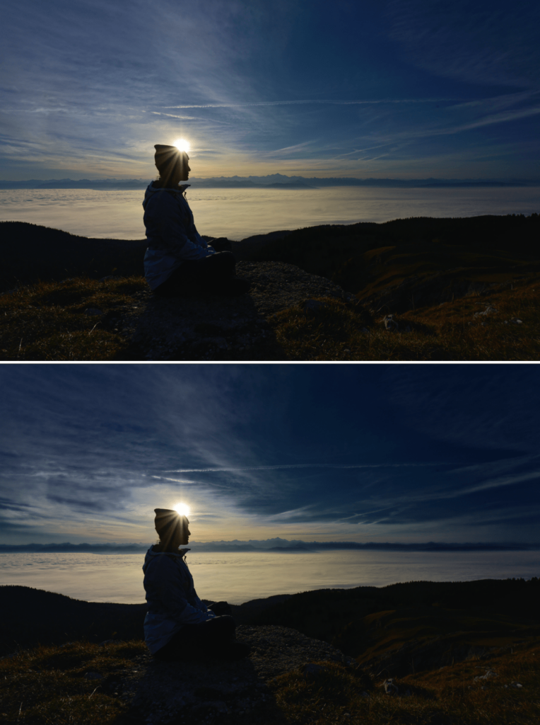
Giving more depth and impact to the sky with the hue mask and a combination of exposure and dehaze corrections.
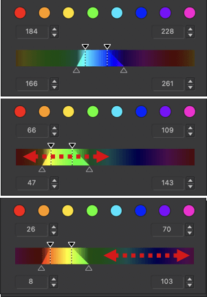
The trapezoid can be moved in the hue range and, if you reach one end, you can also move the hue range with the mouse.
Automatic mask
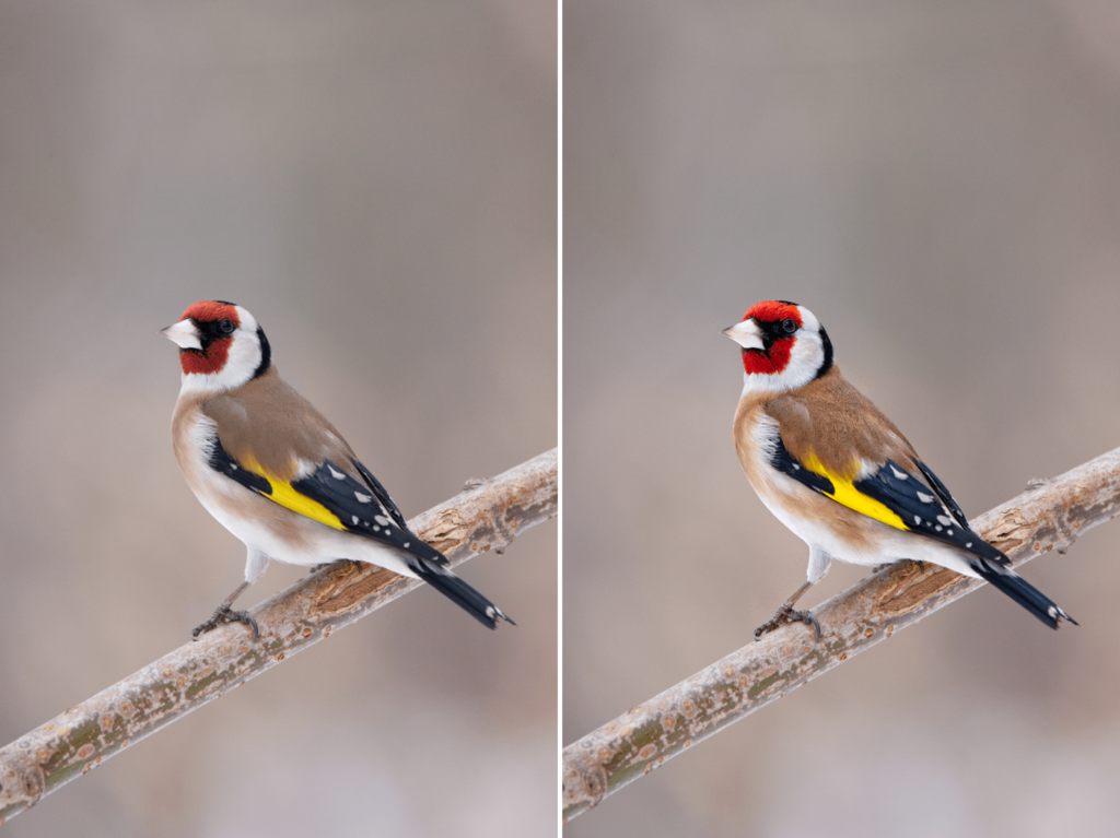
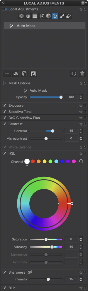
The automatic mask tool lets you paint and apply adjustments in specific areas of the image without going beyond edges, defined by a difference in luminosity, contrast, and color.
Aside from this automatic edge-detection capability, you use it in the same way as the brush. You can even go over an edge, as the adjustment will only be applied inside.
When to use the automatic mask.
You can use the tool to change the color of a vehicle to make it stand out from the surrounding environment, for example. The automatic mask is particularly good for objects or specific elements. To change the appearance of a sky, opt for control points or the graduated filter.
Activating the Automatic Mask
As with the other local adjustment tools, go to the Local Adjustments palette, and click on the Auto Mask button. You can use the automatic mask on an image that already has other local adjustment masks.
When local adjustments are enabled, you can switch from any of the other tools to the Auto Mask using keyboard shortcut Shift+A.
Using the Automatic Mask
Once activated, the automatic mask tool will turn into a brush with a blue circle with a plus sign in the middle.
Click inside the image to place the mask disk containing a brush with an “A” label. The blue border indicates that it is an active mask.
You can apply adjustments using the Equalizer before or after you paint.
You can also apply brush strokes by clicking several times. Even if you brush outside an element in the image, the correction will generally not go beyond its edges. However, if the correction does go beyond the edge (which can occur if certain parts of the element you are retouching blend into the background), use the keyboard shortcut Alt (PC) or Option (Mac) to activate the Eraser.
If the element is textured, the coverage will not be perfect, so use the brush again if this is the case.
The outer circle (light blue) detects the edges.
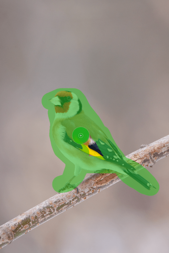
You can adjust the size of the brush with the mouse wheel by holding down Ctrl (PC) or Cmd (Mac).
To view the active mask, check Display Selected Mask in the toolbar below the image.
You cannot use the automatic mask brush to apply a feathered effect.
Managing Automatic Masks
To delete an automatic mask, activate it by clicking on the disk and then pressing the Enter key. If you need to create a separate automatic mask, first deselect the active mask by clicking on the disk, then click on the desired location in the image.
Finally, just as with the Brush, you can move the Aut
Brush
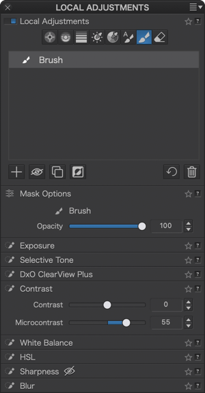
When to use the brush
The brush is a mask that lets you retouch parts of the image by simply painting using your mouse pointer (or graphics tablet, trackpad, etc.).
This universal tool lets you perform a range of tasks, including lightening a backlit subject, enhancing the color of a single flower, or increasing the sharpness of a model’s eyes. The applications are endless, especially since the brush lets you paint continuously (e.g. for lightening an entire silhouette) or subject by subject (e.g. highlighting one eye at a time).
You can also create several brush masks in the image.
Activating the brush
In the Local Adjustments palette, click on the brush tool.
As soon as you have activated local adjustments, you can switch from one of the other tools to the Brush with the keyboard shortcut Shift+B.
Using the brush
The brush tool appears as a blue disk with a brush icon. Click on the part of the image you want to retouch. The active disk for the mask and Equalizer will appear. At this point, you can continue to paint and apply adjustments afterwards, or make your adjustments first and then paint on the image.
Of course, you can use multiple adjustment tools from the Equalizer on the same part of the image. For example, you can lighten an object and also increase its sharpness and micro-contrast.
- You can set the size of the brush by holding down Ctrl (PC) / Cmd (Mac) with the Mouse Wheel; scroll up to increase the diameter and scroll down to reduce it.
- To adjust the amount of feathering, or hardness of the brush edge, use the mouse wheel while holding down the Shift key. Scroll up for a crisper, more defined edge, and down for a softer edge effect.
- The opacity lets you define the maximum level of opacity (or transparency) of the painted area. If you set the opacity at 100%, your adjustments will be applied at 100%, and the area will be completely opaque.
If you set the opacity at 50%, the brush will cap this setting at 50%, and your local adjustments will be only 50% applied. - Flow lets you to define how much “paint” is applied with each brush stroke. If you set the flow to 100%, a single brushstroke will reach the maximum opacity setting selected.
For example, if you set the flow to 13%, the first brushstroke will apply 13% of maximum opacity. A second stroke over the same area will add another 13% of the maximum value (for a total of 26% opacity), and so on until the maximum opacity level of 100% is reached.
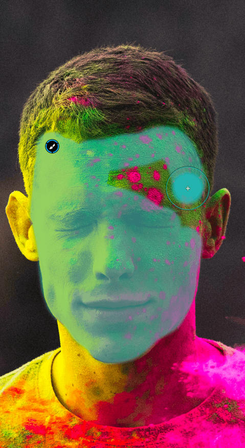
When you use the brush, a blue mask will appear where you’ve applied the tool to help guide you as you retouch the image.
Zoom in for more precision or to paint along an edge. When you are not painting, you can activate or deactivate the blue mask display by clicking on the Display Selected Mask checkbox in the toolbar below the image (macOS only).
Creating and managing masks
You can create as many masks as you want, to retouch specific subjects or to paint separate parts of an image. You can also layer your corrections.
To create a new brush mask, deselect your current mask by clicking inside the circle. Then, place the blue disk with the plus sign wherever you like and then click: a new active mask is created, and you can paint to make your adjustments. To move a Brush Mask within the image, click on the disk of the mask in question, which will automatically activate it, and then drag it with the mouse.
If you want to remove a mask, activate it and then hit backspace (Mac) or the Delete key (PC) on your keyboard.
If you accidently go over an outline or want to fix an error, activate the Eraser by pressing Alt (PC) or Option (Mac), then go back over the active mask. The blue mask helps you see where to erase. You can also adjust the size and feathering.
Finally, to switch back to brush mode, release the Alt/Option key.
Eraser
The eraser lets you refine your local adjustments and correct any errors — for example, if you go over the edges of an object with the brush or the automatic mask. You can also delete or add adjustments depending on the type of mask you’ve selected.
Note: To see examples of using the Eraser with other local adjustment tools, refer to the paragraphs (sections) concerned.
Activating the Eraser
There are two ways to activate the eraser:
- Select the Eraser in the Local Adjustments palette.
- Press the Alt key (PC) or the Option key (Mac) when using the brush or the automatic mask.
In the first case, the mouse pointer turns into an eraser. To change its size, use the mouse wheel while holding down Ctrl (PC) or Cmd (Mac). Hold down the Shift key and use the mouse wheel to change the feathering effect.
Using the Eraser
Select a mask by clicking on its disk. To better see where to apply the eraser, activate the blue mask by checking Display Selected Mask in the toolbar below the image.
Apply the eraser to the local adjustments you want to modify or alter. If you erase an adjustment by mistake, temporarily switch to addition mode by clicking while holding down the Alt key (PC) or Option key (Mac). This will allow you to restore the adjustment. If you want to edit it, you can change the settings in the Equalizer.
To erase something in a different mask, deactivate the active mask (click the disk), then activate the other mask (click the disk to turn the edge blue).
Reminder: The Eraser is always available with the Brush and Auto Mask, by pressing the Alt key (PC) or Option (Mac).
The Watermark palette
Purpose and usefulness of watermarks
DxO PhotoLab lets you add a watermark to your images in the form of text, graphics, or both. The DxO Instant Watermarking tool offers the advantage of a live preview of the watermark in the image, during creation and alteration. Then it is up to you to decide whether or not to add the watermark to your exported images.
The purpose of a Watermark is to:
- Protect your images.
- Mark your images as belonging to you, as an author, a company, or more generally as the owner of the work.
- Sign your images — for example, for an exhibition or publication in a web gallery.
The text or image, if embedded judiciously (avoiding placement too close to the edges), will discourage theft, reuse, or unauthorized republication of your images. On the other hand, an overly conspicuous watermark can also alter and even discourage others from viewing your images.
If you choose an Image watermark, you will need to create it first in an image editing or graphic design program. DxO PhotoLab does not let you create logos and other graphic elements.
A watermark is not a substitute for the author and copyright information in the image metadata; we encourage you to continue to fill in these fields, particularly the Metadata palette.
The Watermark palette
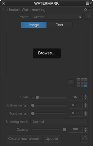
The Watermark palette is located at the very bottom of the right pane of the Customize tab (DxO Advanced workspace) or as a sub-palette at the bottom of the Basic Tools palette. Inactive by default, it is activated as soon as you click on one of the modes (Image or Text); the tools displayed depend on your choice.
When you apply a watermark to an image, it will always be visible, both in the Viewer and in the image browser thumbnail. Although the look of the watermark can be undone — in other words, you can change or replace it at any time — its application will be permanent in exported images.*
* Watermarks will not be applied to images exported using the Export to DNG option (denoising & optical corrections only).
Embedding an image
To embed a watermark image:
- Display your photo in Fit to Screen mode so you can check the size, proportions, and appearance of the watermark in real time.
- In the Watermark sub-palette, select the image mode by clicking the Image button.
- In the Preview window, click on Browse.
- A system dialog box allows you to locate and select your image. Click on Open.
- The watermark image will appear in the Preview window as well as in your photo, depending on the selected position. The name of the file is displayed below the preview window.
- The checkerboard lets you position the image in the center, top, bottom, left, right or corners of your photo; click on one of the 9 blocks to place it where you want it.
- When you select a position other than the center, margin sliders activate in the palette: for example, Left margin for the left position, or Left margin + Top margin for the top left position, etc. These sliders (set to 0 by default) allow you to position your image exactly where you want it in the photo.
- The Rotate watermark button, to the left of the positioning grid, allows you to rotate your image in 90° increments with each click.
- Adjust the image size** with the Scale slider, between 1 and 100 (default value: 15).
- The Blending Mode menu lets you select how the embedded image will blend into the photo. 7 blending modes are available (see section on Blending modes below).
- Use the Opacity slider to play with the transparency of the watermark and thus its presence in your photo.
** Make sure your image file is of a size and resolution high enough to avoid edge potential cropping and degradation of its appearance.
Embedding text
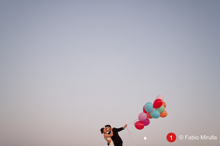
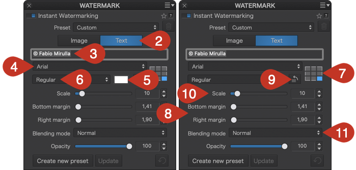
Text is the easiest way to mark your photos with your name or your company name if you are a professional, for example. Unlike images and logos, which you need to create outside of DxO PhotoLab, DxO PhotoLab lets you enter your text directly thanks to the pre-installed fonts of your operating system.
To insert a text watermark:
- Display your photo in Fit to Screen mode so you can check the size, proportions, and appearance of the watermark in real time.
- In the Watermark sub-palette, select text mode by clicking the Text button.
- Click in the input field just below the Image/Text buttons and enter your text, which will also activate all the other tools in the sub- palette. Enter your text and validate with the Enter key; the embedded text will appear in the image.
- Select your favorite font from the drop-down list below the input field (the default font is Arial).
- You can also change the default white of the font by clicking on the white tile, which opens the operating system’s color picker where you can select another color.
- The menu to the left of the tile lets you change the style of your font (bold, italic, etc.).
- The checkerboard lets you position the text in the center, top, bottom, left, right or corners of your photo; click on one of the 9 blocks to place it where you want it.
- When you select a position other than the center, margin sliders will activate in the palette: for example, Left margin for the left position, or Left margin + Top margin for the top left position, etc. These sliders (set to 0 by default) allow you to position your text exactly where you want it in the photo.
- The Rotate watermark button, to the left of the positioning grid, allows you to rotate your text in 90° increments with each click.
- Adjust the size of the text with the Scale slider, between 1 and 100 (default value: 35).
- The Mode menu allows you to choose how the embedded text will blend in relative to your photo. There are seven blending modes available (see below).
- You can use the Opacity slider (set to 100 by default) to play with the transparency and presence of the text in your photo.
For watermarks, there are no prohibited characters, no incompatible fonts, and no limit to the number of characters.
Blending modes
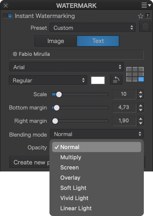
You can control how the embedded watermark, text or image, appears in the image, depending on the colors, brightness, opacity or background you choose. The use of blending modes requires a little experimentation on your part; the result depends largely on the type of watermark, its settings, and the image in which it will be embedded, of course. There are seven different blending modes:
- Normal (default setting)
- Multiply
- Screen
- Overlay
- Soft light
- Vivid light
- Linear light
Embedding an image and text
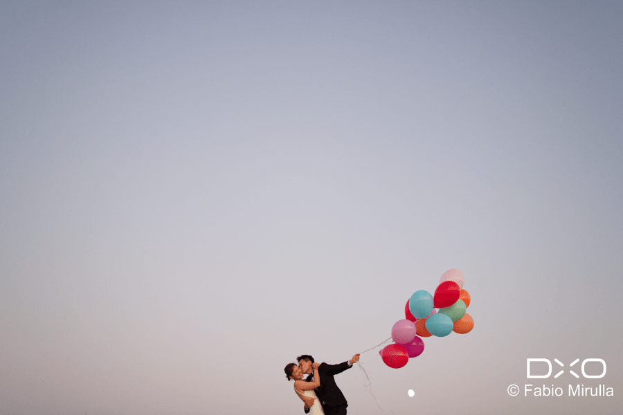
The Watermarking tool offers great flexibility by giving you the possibility of embedding both an image (logo or other) and some text:
- In the Watermark sub-palette, click on the Image button and then follow the same steps as in the Embedding an Image section above.
- Once the image is embedded, click on the Text button, then repeat all the steps in the Embedding Text section.
Creating, applying, and managing watermark presets
If you want to use more than one type of watermark, the sub-palette allows you to create, save, apply, and modify as many watermarks as you want, as presets.
Creating and saving a preset
- Create an image and/or text watermark* by following the instructions detailed in the Embedding an image and/or Embedding text sections above.
- In the sub-palette at the bottom, click Create Preset.
- Enter a unique name in the dialog box that appears and confirm by clicking OK.
- The name of the watermark is displayed in the Preset list at the top of the sub-palette: This is the preset you just created, and it is active.
*You can create a preset that includes both image and text, no matter whether you are in Image or Text mode, both will be taken into account. There is no limit to the number of presets that you can create.
Applying a preset
- In the Preset list, select the desired watermark.
- The watermark will be embedded in the photo.
- The sub-palette shows the settings for the selected watermark.
Changing a preset
- In the Preset list, select the watermark you want to change.
- The watermark will be embedded in the photo.
- The sub-palette shows the settings for the selected watermark.
- Change the settings as desired. To return the settings to the original watermark settings, click on the round-arrow (reset) button.
- To keep the watermark with its changes, click Update.
- To keep the original watermark and its modified version, click Create Preset and enter a new name.
Deleting a preset
- In the Watermark sub-palette, choose the watermark you want to remove from the Preset list.
- Click the trash can button on the right side of the Preset menu.
- A dialog box will ask you to confirm the deletion. In this case, choose OK.
- The watermark disappears from the Preset list.
Applying, exporting, and printing a watermarked photo
Applying a watermark to one or more photos
When you create a watermark, the watermark is displayed in real time on the photo in the Viewer and in the image browser. To apply the watermark to multiple photos at the same time, select the photos in the image browser (in which case, the first selection will be displayed in the Viewer).
Exporting one or more watermarked photos
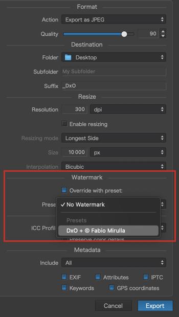
Whatever export mode you choose – disk, application, etc. – the watermark will be applied to your photos, with the following exceptions:
- If you select the mode Export to DNG (denoising and optical corrections only).
- If you select No watermark in the export options (Watermark section, Preset menu).
- If you have checked Replace with a preset in the Watermark section of the export options. In this case, you can replace the watermark with another watermark that you choose from the Preset menu.
Printing a watermarked photo
These are the options when it comes to printing your watermarked photos:
- If printing outside DxO PhotoLab, export the image by applying the watermark.
- If you print while in DxO PhotoLab, the watermark will be applied to your print.
- If you do not want to print the photo with its watermark, disable the Watermark sub-palette beforehand.
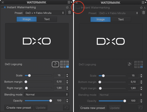
A few tips
Whether or not you should embed a watermark is a matter of much debate. Does the watermark really protect your images and your rights? Does it interfere with the look of your photos? If you decide to embed a watermark, here are some tips:
- Avoid logos and text that look aggressive, high contrast, or have overly strong colors, as they can distract and interfere with the look of your photos.
- Choose a small watermark placed at the edge of the image, but not too close to the edge, because if the photo is reproduced without your permission, it could be easy to crop it out. Use the margin sliders to place your watermark a little further inside the photo and, if possible, at an angle to make cropping more difficult.
- You can also embed a watermark across the width of the image, but with very low opacity so as not to interfere with the look of the photo. Make sure that it is barely visible, knowing that it is easy to reveal by pushing up the brightness and contrast settings.
- If you want to add a copyright symbol (©) to your text, and it is not directly accessible on your keyboard, use the option + g keys on a Mac, and the ASCII code Alt+0168 on a PC.
The DxO ViewPoint palette
About the DxO ViewPoint palette
– This palette only appears if the DxO ViewPoint plugin license has been activated.
– For a complete description of the plugin tools, consult the DxO ViewPoint user guide. Nonetheless, given that the Perspective and ReShape tools reside outside the DxO ViewPoint palette, you will find more about them in your DxO PhotoLab user guide (after this section).
When you install DxO ViewPoint, a specific palette appears in the Customize tab, which offers you the following tools:
- Volume Deformation.
- Miniature Effect.
- ReShape Fusion.
- Flip the image horizontally or vertically.
The DxO ViewPoint Guide tool is only available in the plug-in for Adobe Photoshop and Lightroom Classic, as well as the standalone program.
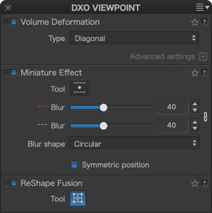
From DxO PhotoLab 6, the Perspective tool is available natively and so is no longer displayed by the DxO ViewPoint plug-in. You can find the Perspective tool in the PhotoLab Geometry palette.
Correcting volume deformation
The deformation of subjects situated on the edges of images is a geometric flaw that is frequently seem in interior, event, and wedding photos. Known as volume deformation, it frequently occurs when using a wide-angle or wide-angle zoom lens to photograph objects, people, or groups of people. The elements on the edges appear elongated or stretched out. The DxO ViewPoint palette lets you correct this phenomenon as well as horizontal/vertical and diagonal distortion.
For more information about the different tools available depending on the version, see the DxO ViewPoint user guide.
Miniature effect (since DxO ViewPoint 3)
The miniature effect simulates a tilt-shift lens that moves the plane of sharpness in an image, lending it the appearance of a scale model or of a diorama in a landscape photo. This effect is even more dramatic in images of urban landscapes when shot from above. The Miniature Effect tool provides great flexibility in the positioning and intensity of the focus areas.
When you activate the Miniature Effect, two gradients of blur appear on the screen (you will see 4 superimposed on the image): the solid lines delineate the area of the image that will remain sharp (generally in the center), and the dotted lines mark the transition zone between sharp and blurry at the top and bottom of the image. You can reposition the miniature effect anywhere in the photo, and you can also rotate it up to 360°.
The intensity of the shape and the blur are adjustable, and you can also deactivate the symmetry between the positions of the two blur gradients, as well as the intensity of the blur symmetry (meaning that you can have a different blur for each gradient).
ReShape Fusion Tool (since DxO ViewPoint 5)
The ReShape tool allows you to modify one or more elements in the image using a deformable point grid. It can be used for a variety of applications:
- Refine, equalize, or alter the proportions of an object.
- Refine geometry corrections (perspective adjustment, volume distortion).
- Compensate for the curvature of a straight line or the horizon.
Additionally, Reshape Fusion offers tools that allow you to make local adjustments to shapes, volumes, horizon, and perspective, while controlling the propagation of corrections and preserving the original framing if you need it.
Flip horizontally/vertically (since DxO ViewPoint 4)
Activating DxO ViewPoint installs two inversion tools into DxO PhotoLab:
- Flip horizontally: inverts the image along the horizontal plane.
- Flip vertically: reverse the image along the vertical plane.
These commands are available either in the Image > Orientation menu, or in the right-click context menu > Orientation. You can combine, as well as reset, them.
Features specific to using DxO ViewPoint in DxO PhotoLab
A certain number of tools and features are specific to using DxO ViewPoint in plugin mode:
- The parts of the background that are cropped out after geometric correction are displayed in gray.
- It is possible to preview the correction directly while using the tool by holding down the Ctrl (PC) or Cmd (Mac) key.
- You can zoom in and navigate within the image using the toolbar. After zooming, you can also temporarily activate the Hand tool to move about in the image by holding down the Space bar.
- The anchor points for the perspective and horizon tools do not have an integrated magnifying loupe.
- The Miniature Effect tool does not let you adjust the blur intensity interactively in the image the way it does in DxO ViewPoint. To adjust the intensity, use the Blur sliders in the Miniature Effect sub-palette.
- The Perspective, ReShape Fusion and Miniature effect tools have an activation button in the top toolbar.
- The Perspective tools are accessible via the Geometry palette.
The DxO FilmPack palette
This palette is displayed only if a DxO FilmPack plugin license has been activated.
The DxO FilmPack palette integrates the film emulations and editing tools specific to DxO FilmPack with your usual workflow in DxO PhotoLab.
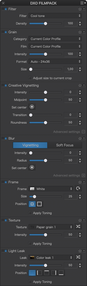
Several palettes and tools are at your disposal:
- Filter: Simulates lens filters.
- DxO FilmPack Grain (PC) / Grain (Mac): Lets you apply a specific grain type from more than sixty films, color as well as B&W, and to set the size of the grain.
- Fine Contrast: adds the Fine Contrast slider to the Contrast sub-palette of DxO PhotoLab.
- Creative vignetting (available only in the ELITE Edition of DxO FilmPack): With this palette, you can modify the amount of light on the edges of an image in order to draw attention to a subject in the center.
- Blur (available only in the ELITE Edition of DxO FilmPack): With this palette, you can create a blurry effect around your subject with Vignetting, and with Soft Focus, you can apply a diffusion effect to your images.
- Frame (available only in the ELITE Edition of DxO FilmPack): Lets you place a frame around your image; different styles are available.
- Texture (available only in the ELITE Edition of DxO FilmPack): Allows you to simulate scratches or tears on analog film negatives.
- Light Leak (available only in the ELITE Edition of DxO FilmPack): Lets you reproduce the effects of aging analog film negatives or problems related to accidental exposure of analog film to light.
For more information on the different tools available, depending on the version and/or edition, see the DxO FilmPack user guide.
Time Machine is an illustrated history of photography by decade, going from the 19th century through to the years 2010-20. In addition to consulting this history, the Time Machine window allows you to directly apply the proposed presets:*
- In the Color Rendering subpalette, click on the Time Machine button.
- Select a period by clicking in the banner at the bottom of the window.
- Each period offers several pages that you can browse using the arrows located above the text.
- Under each illustration, you will find the corresponding renderings, which you can apply directly to the images by clicking on them.
- You can change the rendering as you wish, as the applied settings are reversible.
- To exit Time Machine, click Close.
* Time Machine renderings are also available via the Presets button, in the top right-hand corner of the Organize and Customize tabs.