Correcting Distortion
About Distortion
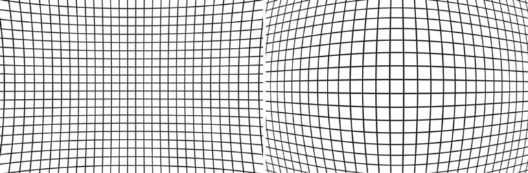
All lenses are affected by varying degrees of distortion. There are two types:
- Barrel: Lines are bent towards the exterior of the image.
- Pincushion: Lines are bent towards the interior of the image.
Some lenses are affected by both phenomena — for example, a zoom lens can display barrel distortion at shorter focal lengths and a pincushion distortion at longer focal lengths, not to mention the various distortions in between.
DxO ViewPoint uses DxO optics modules to correct distortions, so we advise you not to use any lens corrections in the host-application and to disable your camera’s distortion correction tools too.
DxO ViewPoint lets you correct all optical distortions, either automatically, using DxO optics modules, or manually, if the shooting equipment (body and lens) has yet to be supported by a DxO optics module.
In the case of a fish-eye lens, if it is supported by a DxO optics module, typical deformation will be corrected automatically, but you can reduce the degree of correction or even set it to zero using the Intensity slider, if you want to keep the look.
For best results, we recommend correcting distortions before using any of the following tools:
- Volume Deformation.
- Perspective.
- ReShape.
Managing DxO Optics Modules
Downloading and installing DxO Optics Modules
A DxO Optics Module management dialog box appears when you perform an automatic distortion correction. This dialog box displays the most probable optics modules required and offers a choice if there is any ambiguity (when DxO ViewPoint is unable to fully identify the body/lens pair used for shooting.)
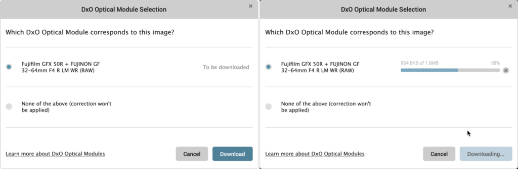
The dialog box also displays the status of the modules: Installed, update available, or to be downloaded.
- Select the corresponding module then click OK.
- A progress bar is displayed; installation and activation are immediate when the download completes. There is no need to restart the program.
A DxO Optics Module is not available
If no DxO optics module is available, automatic correction will not be applied and the Automatic option will be disabled. In which case, you can perform a manual correction.
You have the option of deleting the DxO Optics Module for the image being processed by clicking on the Recycle Bin in the top right corner of the Distortion palette.
Automatically correcting distortion
If your equipment is supported by a DxO Optics Module, you can correct your image automatically.
- Open an image in DxO ViewPoint by clicking File > Open, or drag and drop the image into the application window.
- In the Distortion palette, click the Auto button.
- A dialogue box will indicate whether a DxO Optics Module for your equipment is already installed or whether there one is to download.
- Click on OK to correct the image using the selected DxO Optics Module. The dialog box closes.
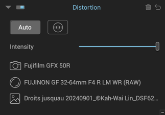
When a DxO Optics Module is installed and taken into account, the Distortion palette displays the following information: camera model, lens model and the name of the original file.
When EXIF metadata is missing
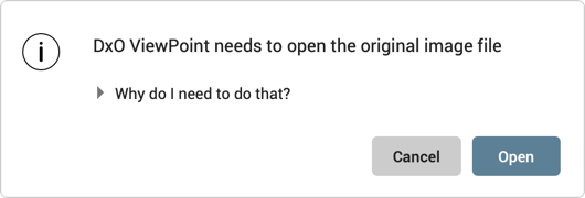
If for some reason DxO ViewPoint cannot find the EXIF metadata information it needs, a dialog box will ask you to locate the original image in order to retrieve the missing information.
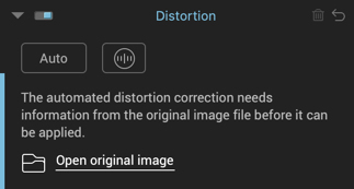
- Open the image in DxO ViewPoint.
- If a dialogue box in the Distortion palette requests access to the original file, click on Open original image.
- Click Open in the dialog box that appears in the DxO ViewPoint window. A system dialog will appear to help you locate the original. You will need to find the JPEG or RAW image file that was loaded directly from your camera before processing.
- After finding and selecting the original image, click on Open. If the corresponding DxO Optics Module is not already installed, a new dialogue box will open and prompt you to download it (if available); otherwise, it will display the information about the shooting equipment and the name of the original file.
- When the corrections have been made, click on Save in the bottom-right. DxO ViewPoint closes and the corrected file is returned to the host application.
Manually correcting distortion
If your shooting equipment is not supported by a DxO Optics Module, you can manually correct your image.
- Open an image in DxO ViewPoint by clicking File > Open, or drag and drop the image into the application window.
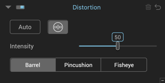
- In the Distortion palette, click the Manual button (a circle with vertical markings).
- Depending on the type of distortion visible in the image, select either Barrel, Pincushion, or Fisheye.
- The correction will be applied immediately.
- If necessary, you can use the Intensity slider to fine-tune the correction.
Correcting volume deformation
About Volume Deformation
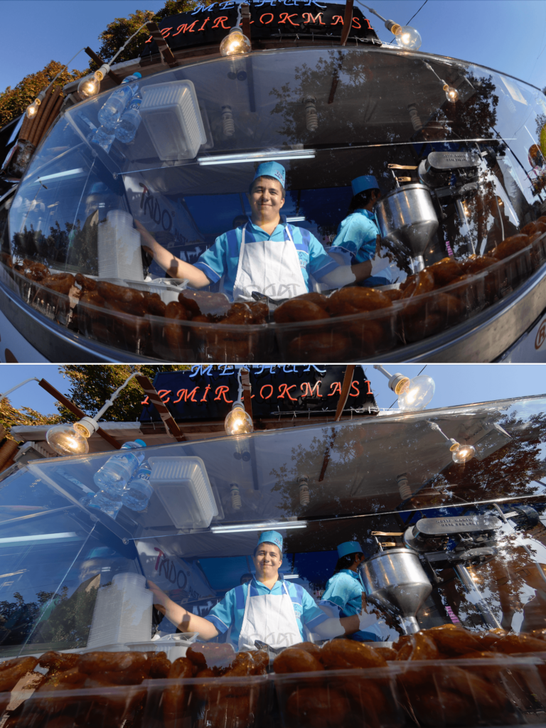
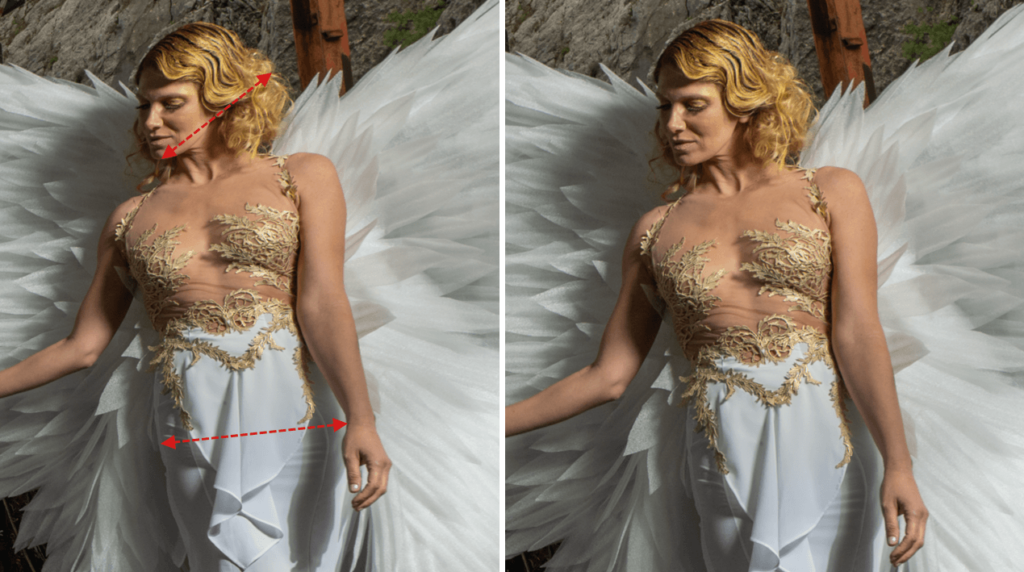
The deformation of a subject at the edge of an image is a geometric flaw that is frequently observed on interior, event, and wedding photos.
Known as volume deformation, it frequently occurs when using a wide-angle, or wide-angle zoom, lens to photograph objects, people, or groups of people. Elements at the edges of the image appear distorted and stretched.
Identify the type of volume deformation
Look carefully at your image to determine the kind of distortion affecting it:
If spherical objects close to the edge of your image appear stretched or flattened along a vertical or horizontal axis then your image is suffering from volume deformation. In this case, use the horizontal/vertical correction tool.

If objects seem to be stretched towards the corners of the image, then you are dealing with diagonal volume deformation, in which case you will need to use the diagonal correction tool.
Correcting horizontal/vertical deformation
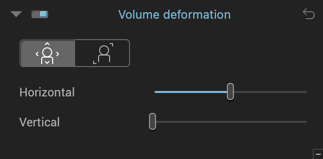
To correct horizontal or vertical volume deformation:
- After opening your image in DxO ViewPoint, activate horizontal or vertical volume deformation correction by clicking the button on the left.
- The correction is automatically and immediately applied to the image.
You can use the sliders to adjust the settings :
- The Horizontal slider stretches the image content toward the edge of the photo (slider to the left) or compresses it toward the center (slider to the right). The default value is 100 (slider in center).
- The Vertical slider flattens the image content vertically. Its default value is 0 (slider on the left).
Diagonal deformation
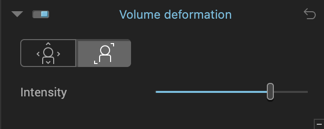
To correct diagonal volume deformation:
- After opening your image in DxO ViewPoint, activate diagonal volume distortion correction by clicking the button on the right.
- The correction is automatically and immediately applied to the image.
For best results
If in doubt, try using both corrections to see which gives you the best result.
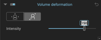
If necessary, you can manually fine-tune the automatic correction by adjusting the Intensity slider. By moving the slider to the left, the image will be progressively stretched and distorted toward the center, moving it to the right will stretch and distort it toward the edges. The default setting for this slider is 150.
You can also click on the number and modify it directly. You can reset the slider to its default setting by simply double-clicking it.
Fixing perspective
About perspective
In architecture, the point of view on a building often forces the photographer to shoot from a high or low angle. In such cases, straight lines in the subject will look warped, especially around the edges of the image.
DxO Viewpoint features tools to let you automatically correct perspectives, vertical parallels, horizontal parallels, force a rectangle, as well as perform an 8-point correction (independent on each side.)
Functions common to Perspective and Horizon tools
A number of options and features are shared by both the Perspective and Horizon tools, since they employ the same straightening lines.
- The lines can be moved, tilted, shortened, or extended with the mouse.
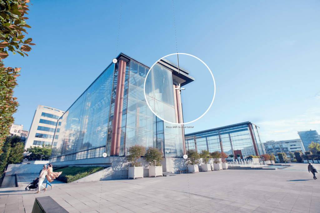
- Use the anchor points at each end of the line to position it. When you click and drag, the pointer turns into a magnifying loupe for greater precision.
- You can slow down the mouse pointer by holding down the Shift key as you position the anchor point.
- Anchor points can be placed with precision by using the arrow keys on your keyboard (click on the anchor point to activate it).
- An active anchor point is indicated by a dark gray circle.
- Hit the tab key to switch from one adjustment line to the other.
- Once you have adjusted the perspective or horizon, the image will be cropped so, the lost background is indicated by a dark translucent mask. A steeply-angled shot will require such cropping that it may cut off parts of subjects that are tightly framed.
- When using the 2 line (Force parallels and Rectangle) or 3 line (8 point) tools, the automatic preview checkbox In the toolbar lets you display the corrections in real time. The automatic preview is only available with the Perspective tools.
- You can also see the corrections in real time by pressing the Cmd (Mac) or Ctrl (PC) key while moving an anchor point. The preview appears after you release the mouse button.
- Alternatively, you can simply click Preview after you have positioned your adjustment lines.
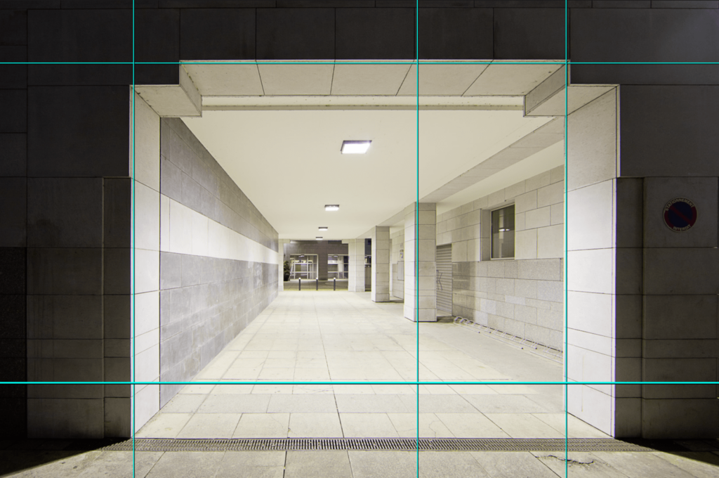
- You can display the composition grid to check that the main elements of your image have been straightened correctly, rather than relying on the naked-eye.
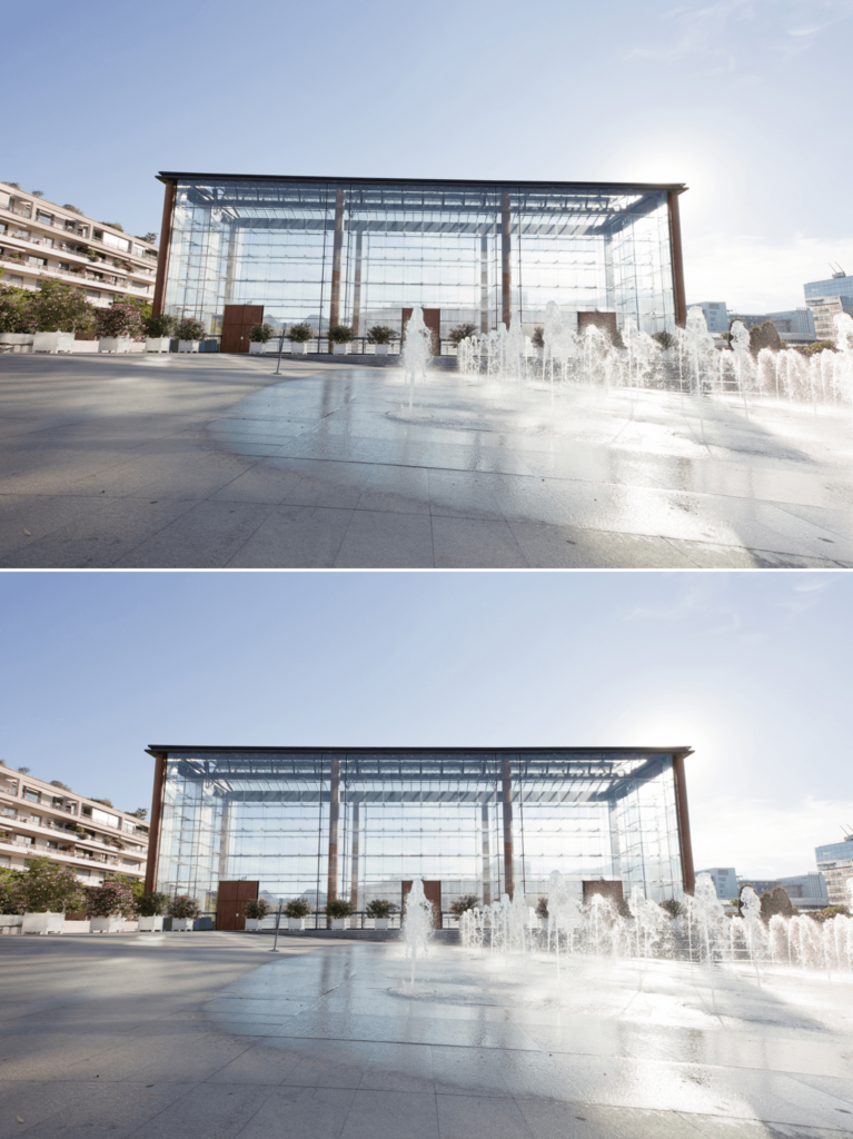
Automatically fixing perspective
DxO ViewPoint lets you automatically straighten perspectives as well as manually alter the corrections as needed. Automatic corrections are preserved if you then decide to go into one of the manual modes (Forcing parallels, Rectangle, and 8 points).
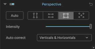
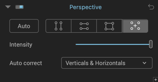
After opening the image in DxO ViewPoint, go to the Perspectives palette and click the Auto button, by default DxO ViewPoint will automatically correct verticals and horizontals.
If you are not satisfied with the result, you can select one of two different modes within the Auto correction palette, Verticals only or Horizontals only; the correction will be applied as soon as you select it from the drop-down menu.
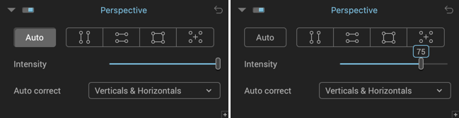
You can use the Intensity slider to adjust the automatic correction, or you can use the advanced settings to modify the perspective (see the Advanced settings section).
To reset the perspective settings, click on the cancel button (curved back arrow) in the top right-hand corner of the palette.
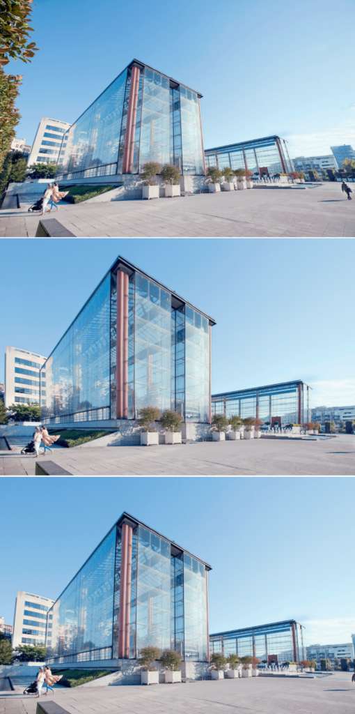
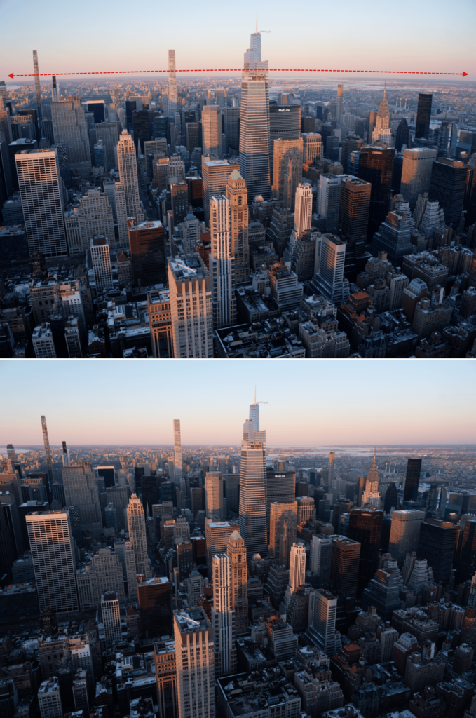
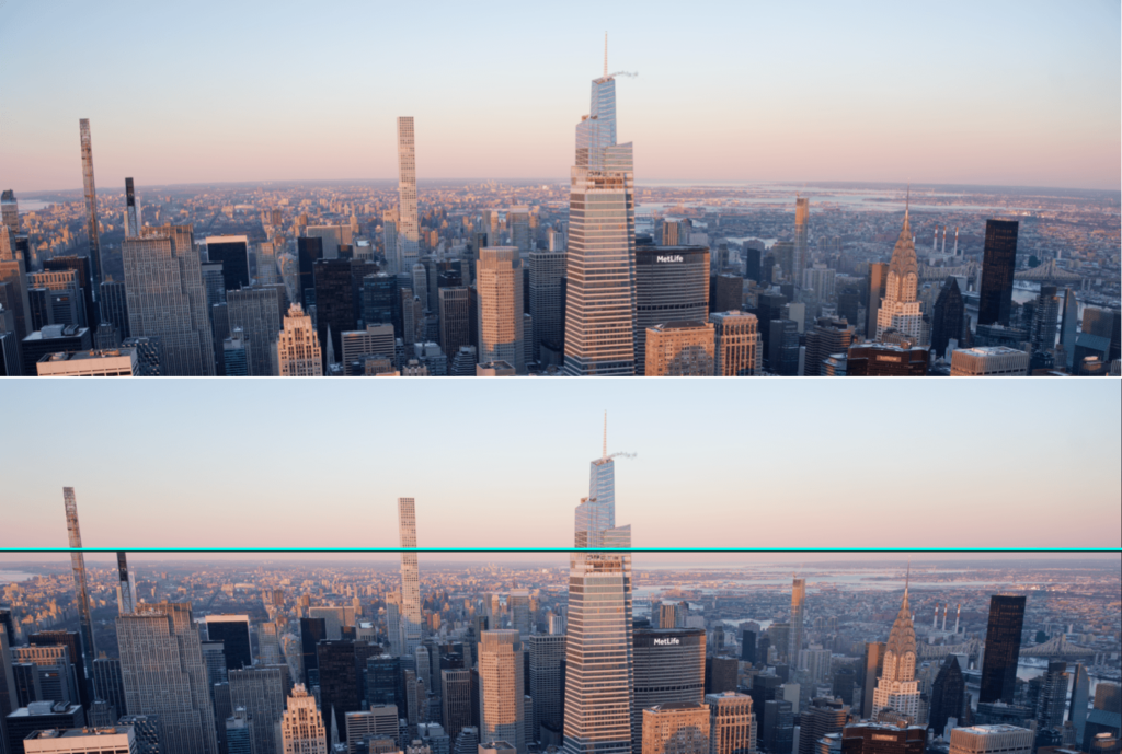
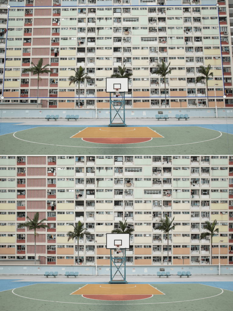
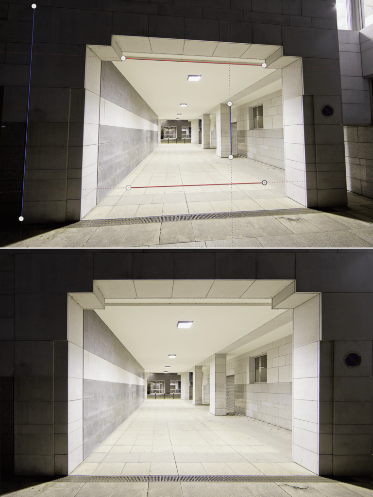
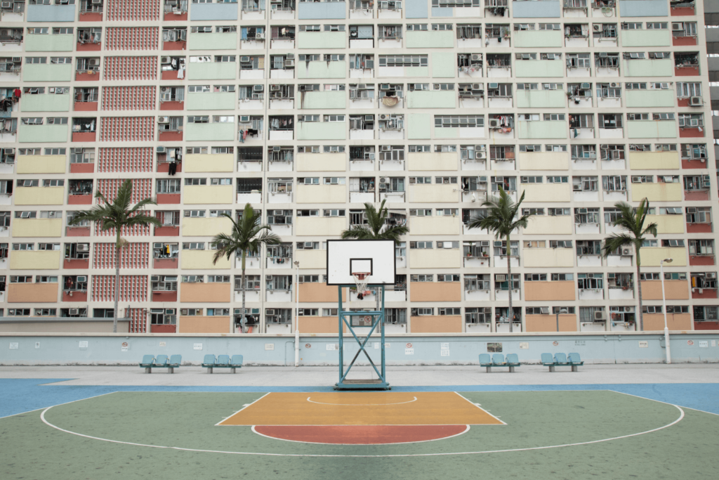
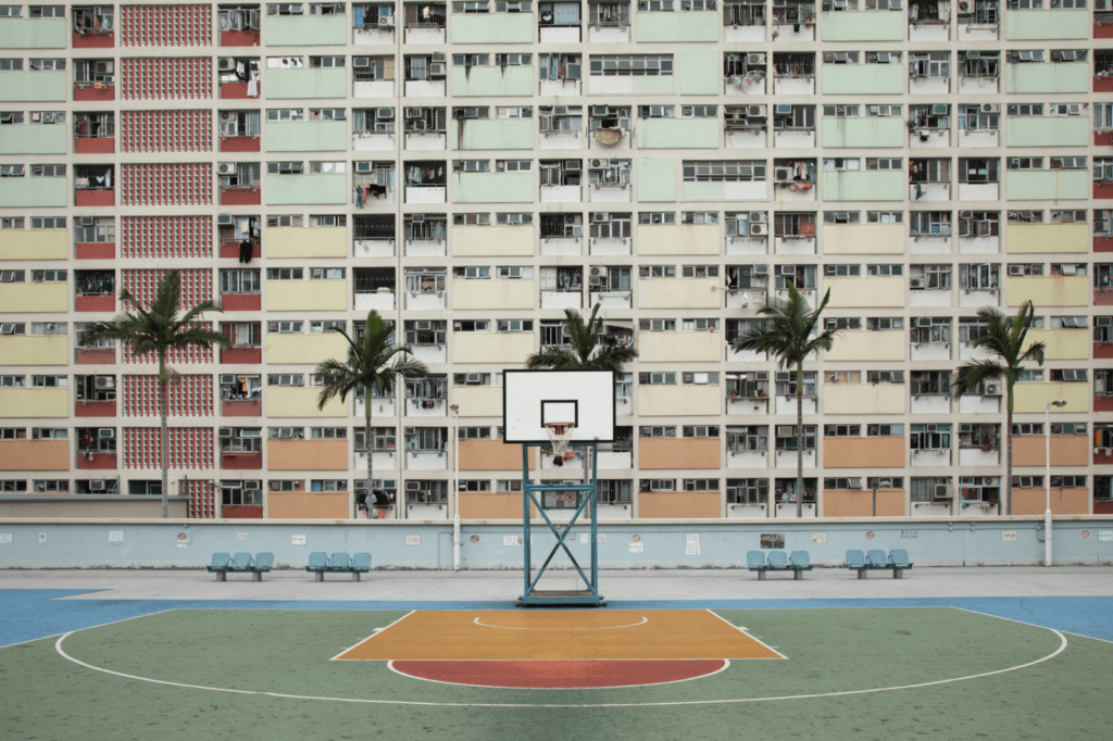
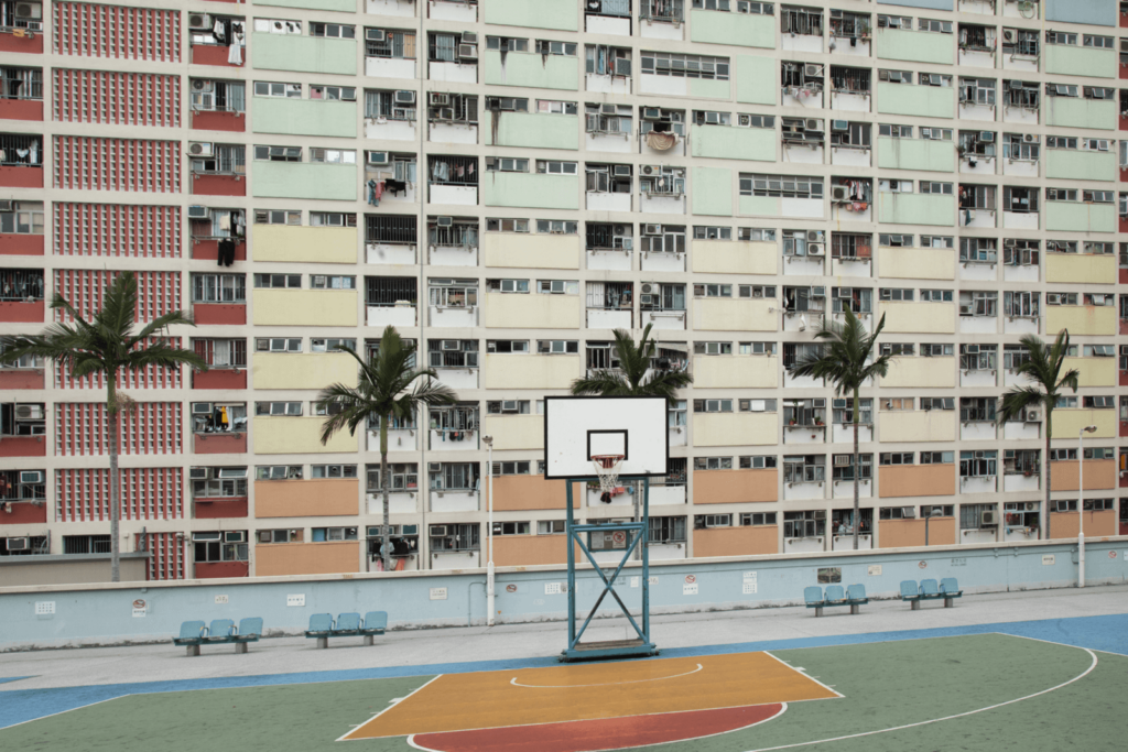
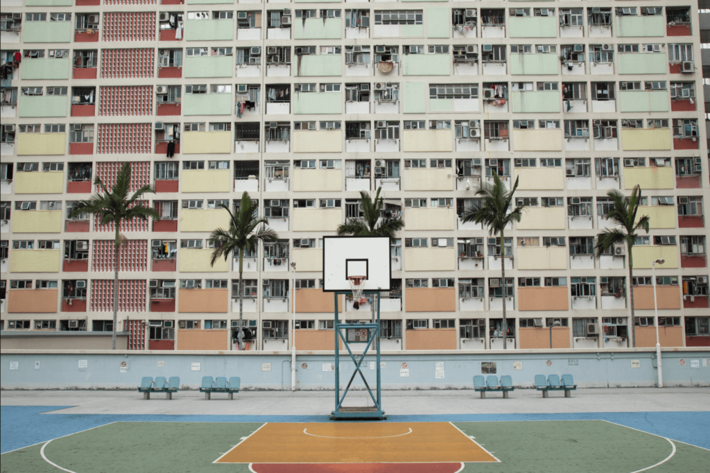
Original image (top), Auto mode (center), intensity set at 75 (bottom).
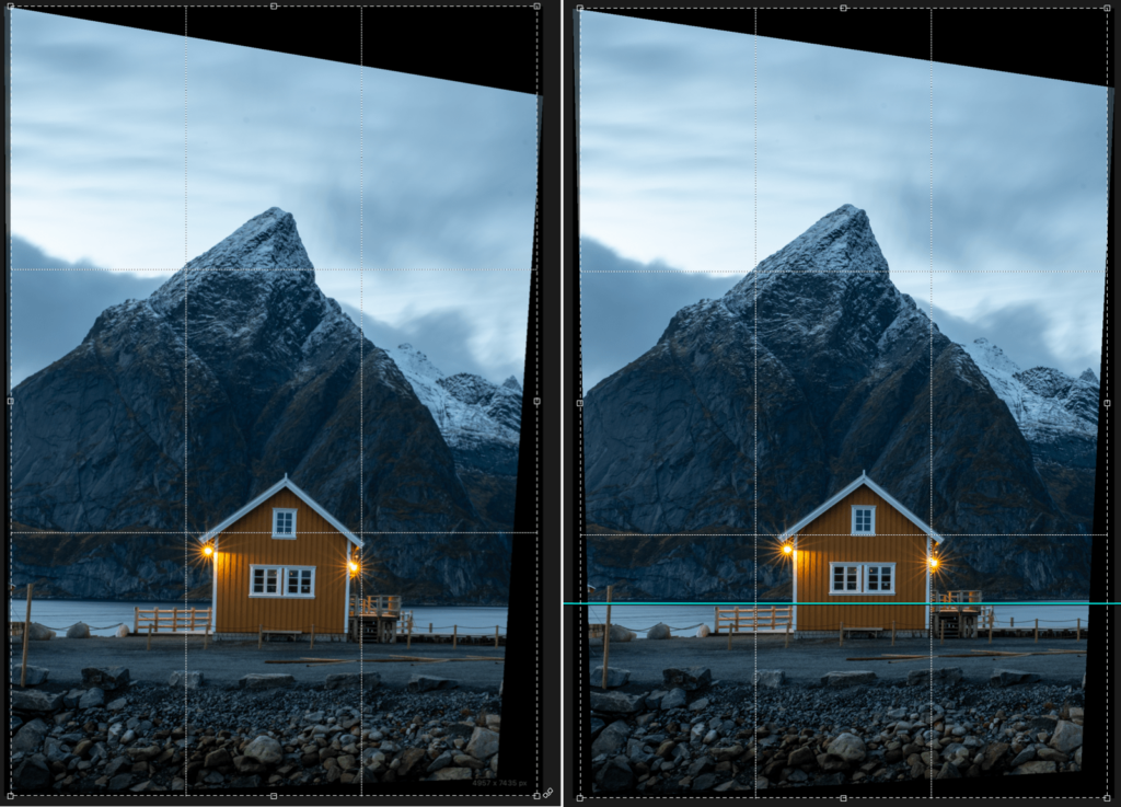
Forcing parallel verticals
To correct receding lines and restore verticals:
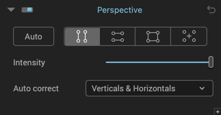
- After opening your image in DxO ViewPoint, go to the Perspective palette and click the Force vertical parallels button.
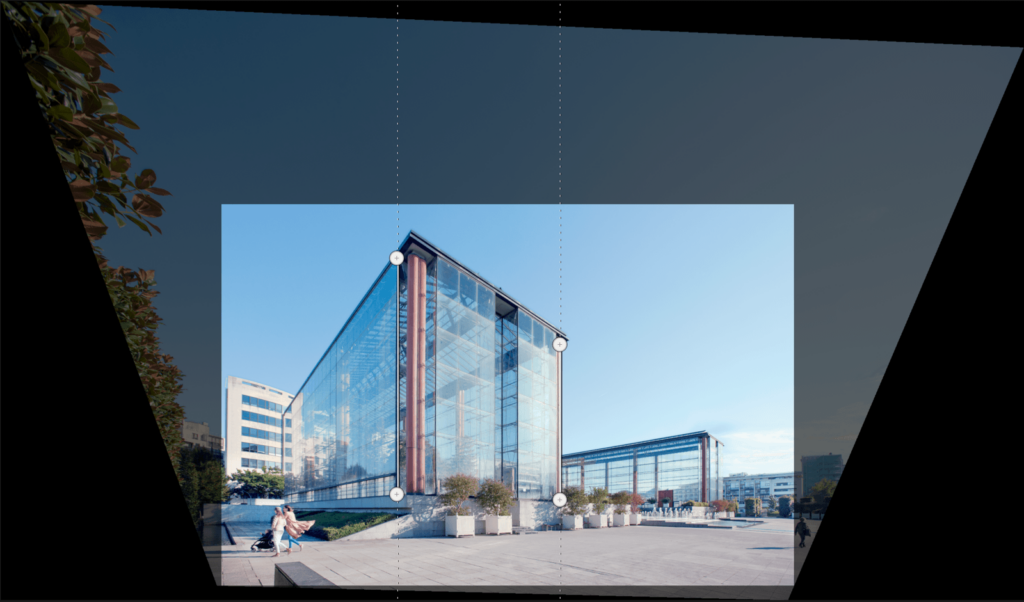
- Two vertical lines, each one with two circular anchor points, will be superimposed on your image.
- Choose two vertical reference elements in your image, preferably located on the same plane, for optimal correction.
- Place the mouse pointer on one of the anchor points. Click on an anchor point to select it: a magnifying Loupe will appear to help you place the anchor point with greater precision. Move the anchor point to one of the ends of your reference element.
- Place the second anchor point so that it traces the line of your vertical element. Follow the same procedure for the second line.
- Check your correction with automatic preview enabled or by clicking on the Preview button in the toolbar (the transparent dark areas indicate the portions of image that will be lost in cropping).
- To approve and apply the correction, click the Apply button on the lower toolbar.
Forcing parallel horizontals
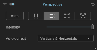
Forcing parallel horizontals follows the same principle as forcing parallel verticals except that the reference lines are horizontal, letting you align and level, for example, the top and bottom of a building, a window frame, or a door. Here’s how to proceed:
- To activate the correction for horizontal perspectives, click on the Force Horizontal Parallel button. Two horizontal lines with two circular anchor points will be superimposed on your image.
- Choose two horizontal reference elements in your image.
- Place the mouse pointer on one of the anchor points. Click on the anchor point to grab and move it to one of the ends of your reference element. Move the second anchor point so as follow the line of your horizontal element. Do the same with the second line.
- Check your correction with automatic preview enabled or by clicking on the Preview button in the toolbar (the transparent dark areas indicate the portions of image that will be lost in cropping).
- To approve and apply the correction, click the Apply button on the lower toolbar.
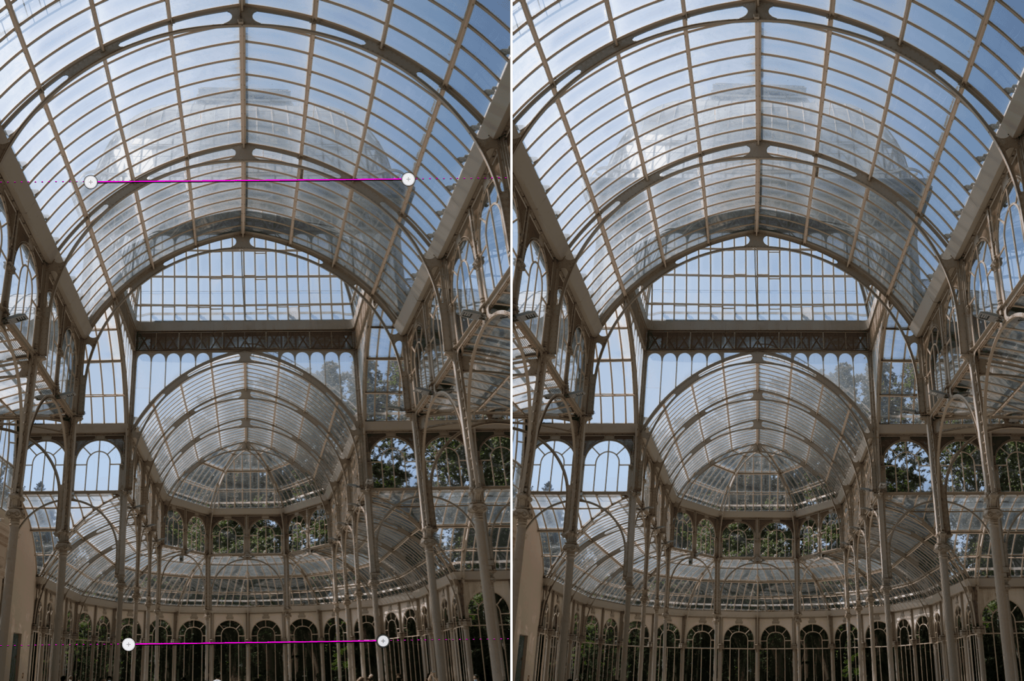
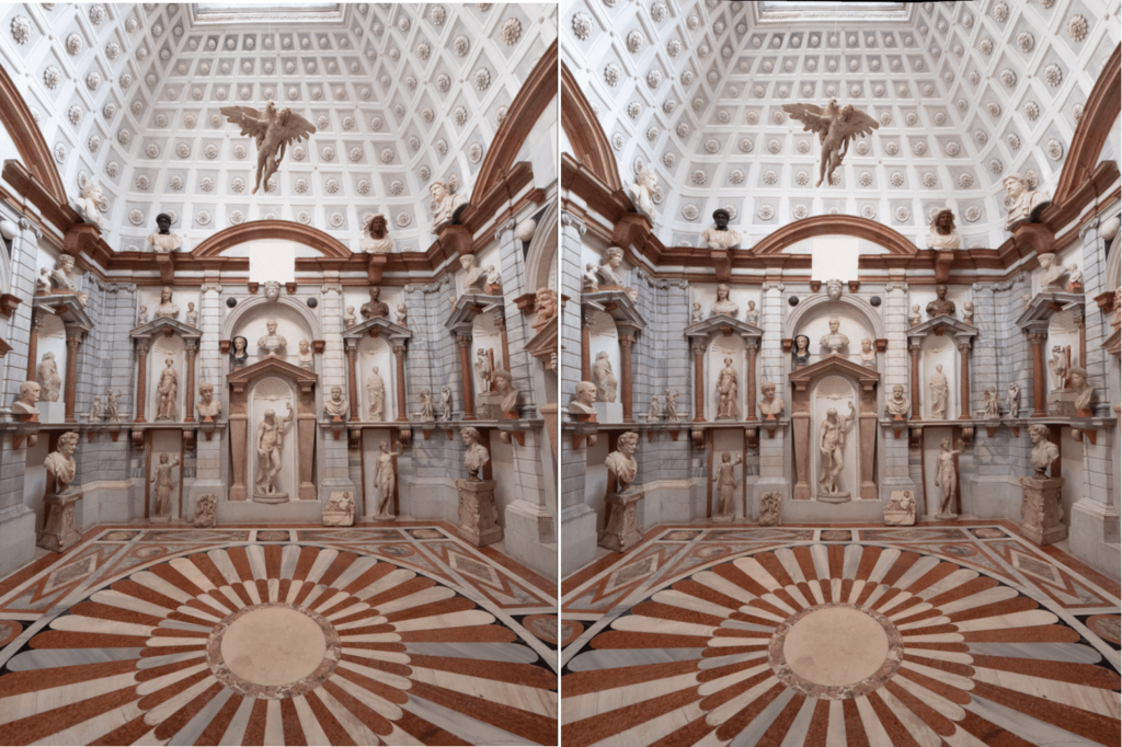
Forcing a rectangle
A third perspective correction function lets you use a reference rectangle for simultaneous correction of vertical and horizontal perspectives, for each side. The applications are numerous: you can restore warped forms to their original shapes in a scene, or straighten an interior space (such as an airport arrivals hall, a museum, or a palace) that was taken at a steep angle or with a tilt when it was shot. To force a rectangle:
- To activate the correction, click on the Rectangle button.
- You can move all four lines: place the anchor points on the axes of the vertical and horizontal reference lines in the image (ideally they should share the same shooting distance, that is – be equidistant from the camera lens).
- Check your correction with automatic preview enabled or by clicking on the Preview button in the toolbar (the transparent dark areas indicate the portions of image that will be lost in cropping).
- To approve and apply the correction, click the Apply button on the lower toolbar.
Moving one anchor point on the Rectangle affects both a vertical and a horizontal line.
8-point correction
8-point perspective correction uses the same principle as Force rectangle, but you can position the lines independently of each other in different planes, which gives you greater flexibility in complex correction situations, such as when the elements to be straightened are at different distances from the camera. 8-point correction works as follows:
- To activate the correction, click on the 8-point button.
- Position the lines on your reference verticals and horizontals, even if they are not on the same plane (the same distance from the lens).
- Check your correction with automatic preview enabled or by clicking on the Preview button in the toolbar (the transparent dark areas indicate the portions of image that will be lost in cropping).
- To approve and apply the correction, click the Apply button on the lower toolbar.
Perspective Sliders
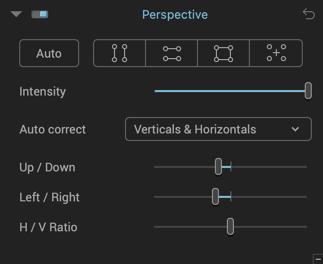
The Perspective palette provides four sliders for fine-tuning correction settings:
- Intensity: This slider, with a default value of 100, helps you find the best compromise between possible corrections and the most natural rendering. You can fine-tune how natural the perspective correction looks by, for example, setting the Intensity slider to 75 instead of 100. (Of course, the setting will depend on the subject and on the type of rendering you are looking for).
- Up/Down: Turns the image on a horizontal axis. If the image lacks reference lines, use this option to correct a shot that was not taken in perfect line with the subject.
- Left/Right: Turns the image around a vertical axis.
- H/V Ratio: This slider lets you fix distortions that sometimes accompany perspective corrections. The default value is 0. Moved to the left, the image is compressed vertically; moved to the right, the image is compressed horizontally.
For the Perspective palette, refer to the Warning Message section for more information about messages concerning the absence of EXIF data and the impossibility of performing an automatic correction of the H/V aspect ratio.
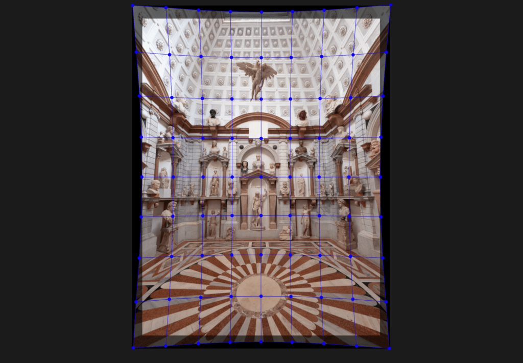
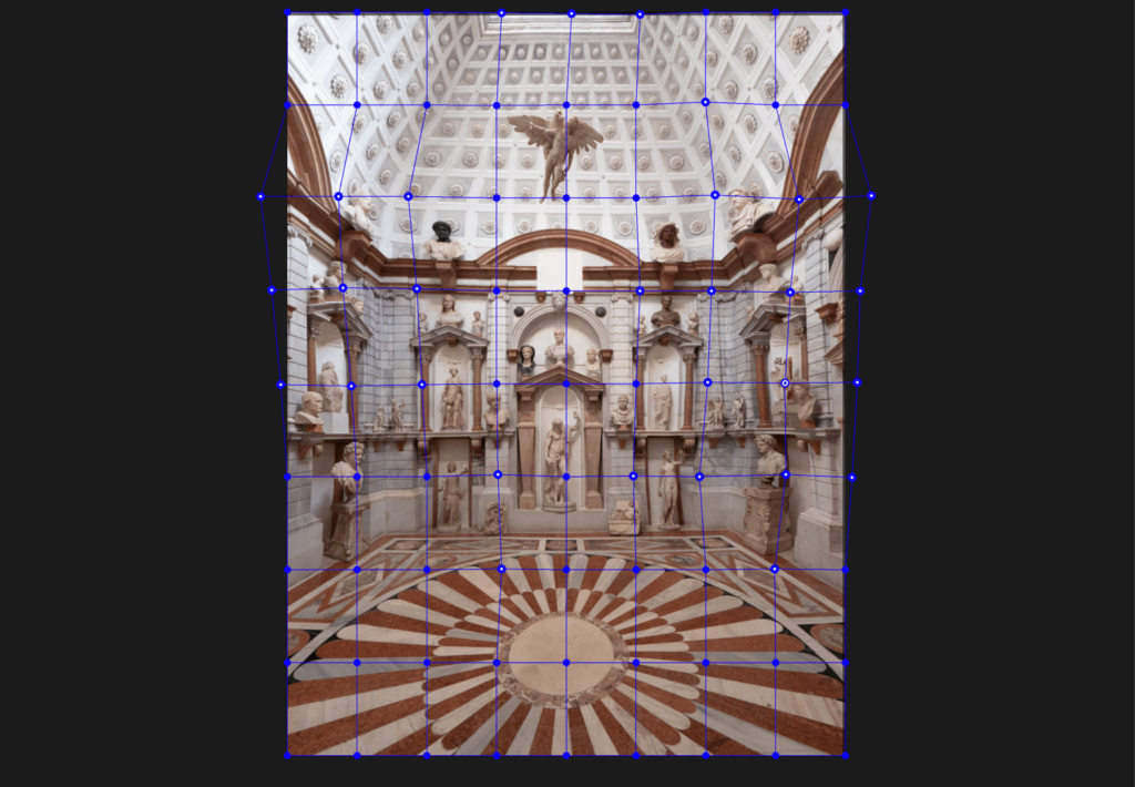
ReShape Tool
About the ReShape Tool
The ReShape tool lets you locally modify one or more elements in the image, using a deformable point grid. It has various uses:
- Refine, equalize, or alter the proportions of an object.
- Refine geometry corrections (perspective adjustment, volume distortion).
- Compensate for the curvature of a straight line or the horizon.
There are all sorts of uses for all types of images: landscape, architecture, still life, portrait, etc. As with other DxO ViewPoint tools, all corrections and distortions applied to the original images are reversible; only saved images will have been definitively modified.
Interface
Palette
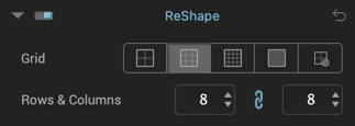
The ReShape palette contains the following elements:
- Grid Presets: These 4 buttons let you select a predefined grid in rows and columns 4 x 4, 8 x 8, 16 x 16, or 32 x 32.
- Customized: This button lets you choose the number of rows and columns (see next point).
- Rows and Columns: These fields indicate the number of rows and columns in your grid, you can change them by typing numbers directly into the fields or by clicking on the up/down arrows. The minimum number is 1, the maximum is 32.
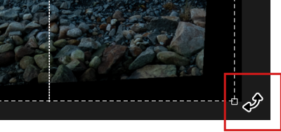
- Unlink: clicking on the chain icon in between the Rows and Columns fields disassociates the number of rows from the number of columns so you can get an 8 x 16, 24 x 2 grid, etc. (up to 32 in each direction.) To relink the Lines and Columns, click on the chain icon again.
The lower toolbar

In addition to the Reset and Apply buttons, the toolbar lets you change the color of the line. Line color: clicking on the blue tile opens a color picker to change the color of the grid lines to alter their visibility relative to the colors and brightnesses in the image.
How to use
Using the ReShape tool is easy: just grab an intersection point where any two lines meet to distort the image in that place. The points have 3 states:
- Blue: unused and inactive.
- Blue-white-blue: active point, currently in use.
- Blue with white dot: inactive modified point.
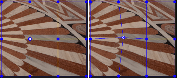
Right: a modified active point.
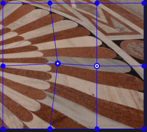
Blue-white-blue point: active point.
You can move a point in any direction and the further you go the more pronounced the locally applied distortion will be.
Each active point or group of active points can be moved as follows:
- By using the mouse, for all directions.
- Using the arrow keys (Up, Down, Left, Right) on the keyboard. Diagonal movement is possible by simultaneously holding down 2 keys at once (e.g. Left and Up to move it at an angle of 45°). The point will move when you hold down a key, and stop when you release it. The point moves in increments of 1 pixel but if you hold down the Shift key the point will move in increments of 10 pixels.
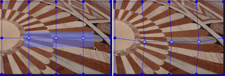
Each point is completely independent from the others, but you can create a group of points by dragging a rectangle over them with the mouse. You can only create and use one group of points at a time so if you create another group of points this will replace the previous group (but the points will be marked as modified).
To correct small items or localized elements, you can increase the number of points by adding rows and columns to the grid. Similarly, you should consider reducing the number of points when dealing with larger elements.
Large-scale corrections and corrections near the edges may result in distortions that force you to reframe the image (cropping areas are shown in black).
Be careful, any corrections you make with the Perspective tool will have an effect on the shape of the grid.
Indeed, your image will get distorted, creating black areas (without content), and will need cropping. If you apply the ReShape tool following this, the grid will cover the image as it really is (deformed) and so will not be based on the cropped version.
IMPORTANT: If you decide to change the size of the grid, this will reset the corrections.
Leveling the horizon
About the horizon
A common flaw in landscape photography: the horizon is off by a few degrees due to slight camera tilt when the picture was taken. Similarly, vertical elements such as poles or trees appear tilted. The solution to this problem is simple: adjust the entire image by a few degrees.
The Horizon tool functions in exactly the same way as the Perspective tool, please refer to the beginning of the Perspective chapter for a description of common tools and functions.
Note that you can also adjust the horizon with the Crop tool.
Automatically leveling the horizon
To level the horizon automatically, go to the Horizon palette and click on the Auto button.
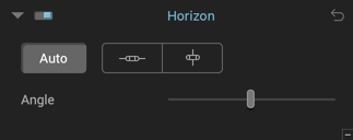
If you are not satisfied with the result, you can:
- Use the Angle slider to adjust the correction, either by moving the slider or by entering a value in the box that appears above the slider.
- Use manual leveling.
Leveling the horizon manually
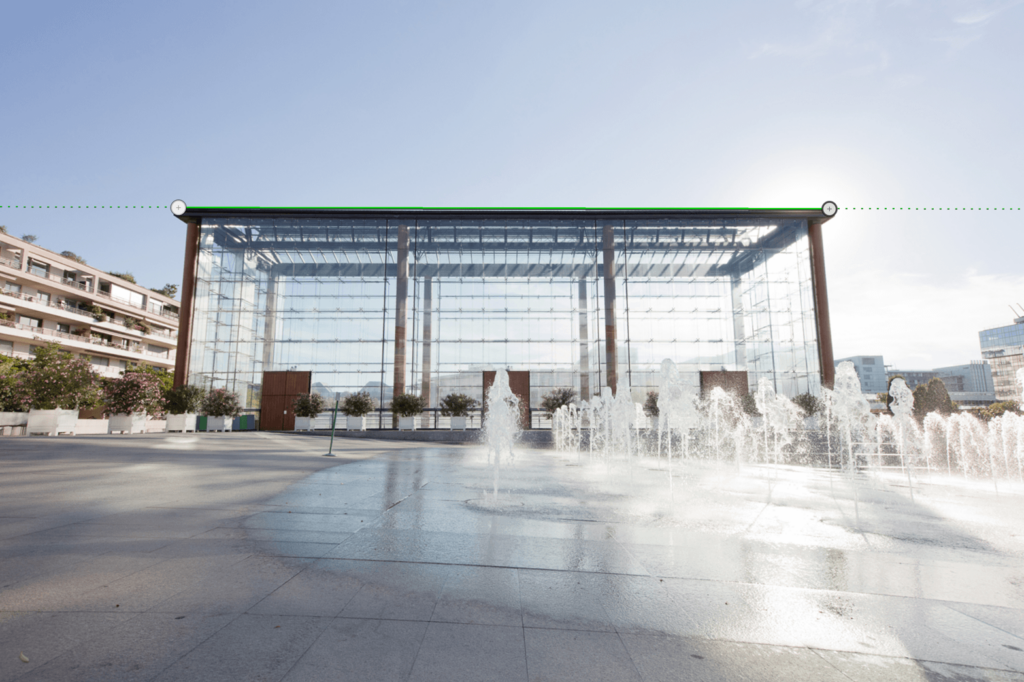
Level the horizon by tracing a line
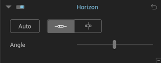
To adjust the horizon manually, you can use both horizontal and vertical references:
- To activate the tool, click on the Horizontal Level or Vertical Level button in the Horizon palette.
- A horizontal or vertical line with two circular anchor points will be superimposed on your image.
- Place the mouse pointer on one of the anchor points. Click on the anchor point to grab and move it to one of the ends of your reference element. Move the second anchor point to follow the line of your horizontal or vertical element.
- When you click on an anchor point, the magnifying Loupe displays so you can place the anchor point more precisely.
- Check your correction with automatic preview enabled or by clicking on the Preview button in the toolbar (the transparent dark areas indicate the portions of image that will be lost in cropping).
- To approve and apply the correction, click the Apply button on the lower toolbar.
Using the angle Slider to level the Horizon
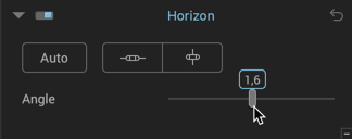
With the Angle slider, you can adjust the rotation of the image in two ways:
- By moving the slider left or right to tilt the image one way or the other.
- By entering a number into the field above the slider handle. Add a – (minus) sign to tilt left.

Cropping an image
About Cropping
The corrections done using the Distortion, Volume deformation, Perspective, and Horizon tools include an automatic crop feature that maximizes the visible field of the image.
Using the ReShape tool can lead to needing to crop the image. Whether cropping automatically or manually, DxO ViewPoint automatically detects the orientation of the cropping area.
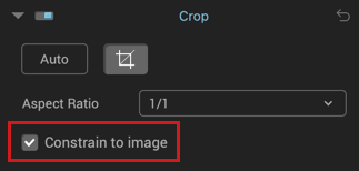
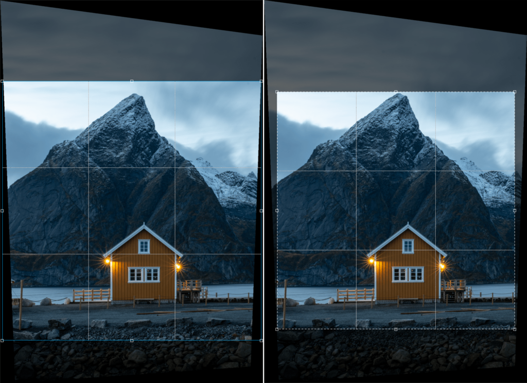
The crop grid is divided into thirds and, if your crop makes it smaller than the image, you can move it around using the mouse. To ensure it cannot be made any bigger than the image, check the Constrain to image box.
Cropping tool lower toolbar

- Show grid checkbox: enables or disables the 3 x 3 cropping grid.
- Mask Opacity: This slider controls the brightness of the areas of the image that will be removed after cropping.
Automatically cropping an image
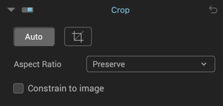
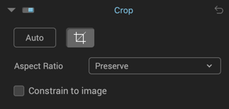
After adjusting the perspective or horizon of your image in DxO ViewPoint, go to the Crop palette and click the Crop button. An adjustable grid will be superimposed on your image.
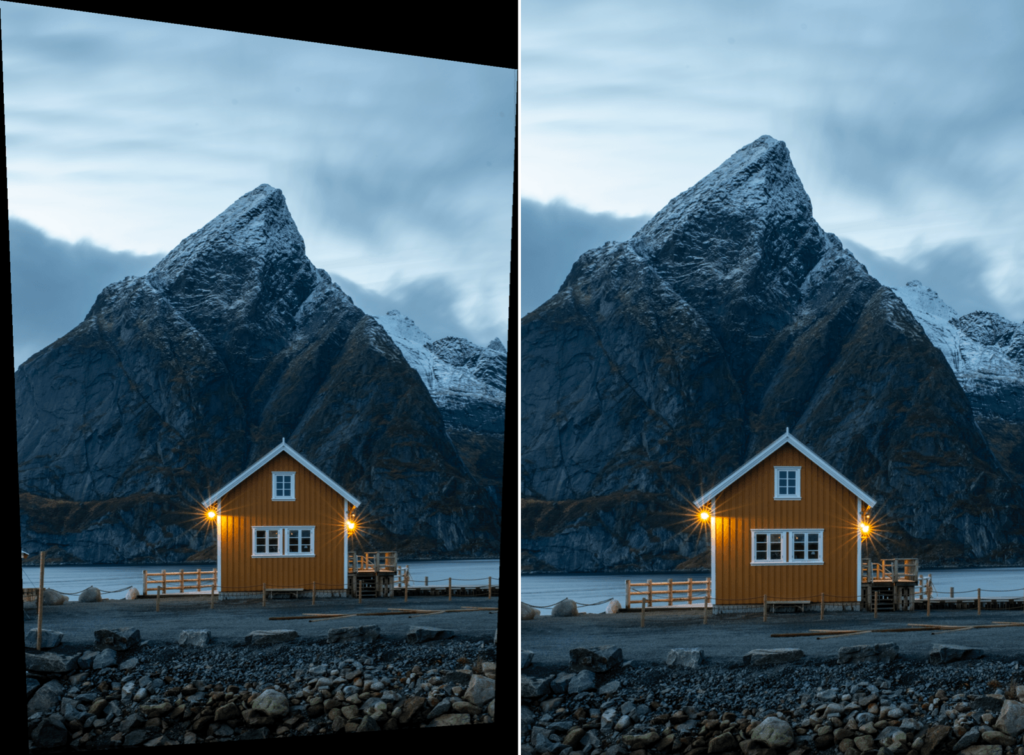
- Click the Auto button. In this mode DxO ViewPoint calculates the area of the image that can be preserved while displaying dark zones that indicate which parts will be lost from the original image.
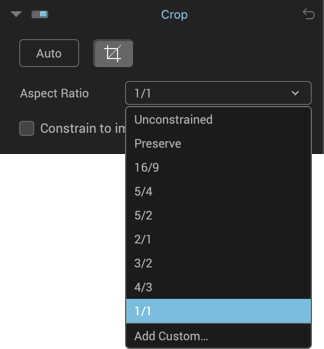
- Several formats are offered in the Aspect Ratio drop-down menu: 16/9 (TV format), 5/4, 5/2, 2/1, 3/2 (APS-C reflex and full-format cameras), 4/3 (compact camera format), and 1/1 (square format):
- By clicking on Preserve in the Aspect Ratio drop-down menu, you will preserve the proportions of the original image.
- By selecting Unconstrained, you can manually apply a correction.
- By selecting Add Custom, you can enter the pixel values (for height and width) of your choice and define the proportions of the custom crop.
- Select the format you would like: the grid superimposed on your image will be automatically modified. By clicking on the grid, you can change the position of the frame and adapt it to the composition of your image.
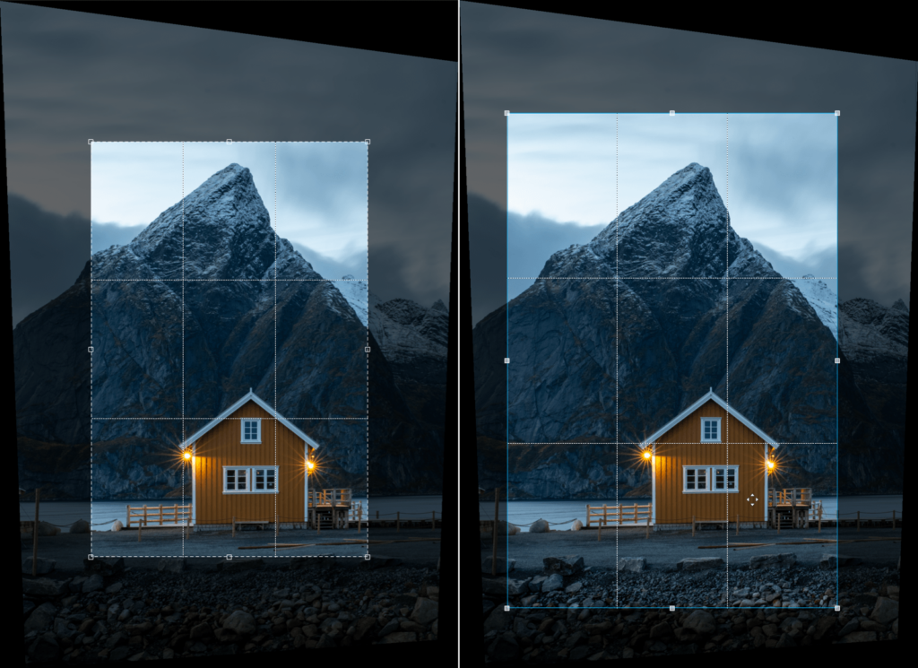
- By checking the Constrain to image box, the frame is automatically confined to the part of the image being worked on, so as to avoid having any dark zones superimposed on the perspective corrections.
- To apply the crop, click on the Apply button in the lower toolbar.
Manually cropping an image
Click on the Crop button in the Crop palette. The adjustable grid will be superimposed on your image. To freely adjust the proportions of the final image, select unconstrained from the Correction drop-down menu.
Adjust the dimensions of the crop by grabbing the resizing handles found in the corners and on the sides of the grid. You can also alter the overall framing to change the composition of your image by grabbing the center of the grid and dragging it to a new position.
You can use the arrow keys on your keyboard to adjust the position of the crop zone.
Leveling the Horizon with the Crop Tool
Although the Horizon tool lets you straighten your images, you can also do this using the crop grid:
- After activating the Crop tool, place the mouse on one of the four corners of the grid.
- The pointer takes the form of a curved arrow to let you tilt the image left or right with the mouse. The grid will not actually move as it is the image that rotates when the mouse button is released.
Miniature Effect
About the miniature effect
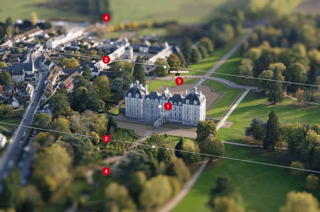
The miniature effect simulates tilting a swing-shift lens to move the image’s focal plane and give the image the appearance of a model, diorama or landscape photograph. This effect is particularly dramatic on images of urban landscapes shot from above.
The DxO ViewPoint Miniature Effect tool offers a flexible way of creating blurred areas of varying intensity in your image.
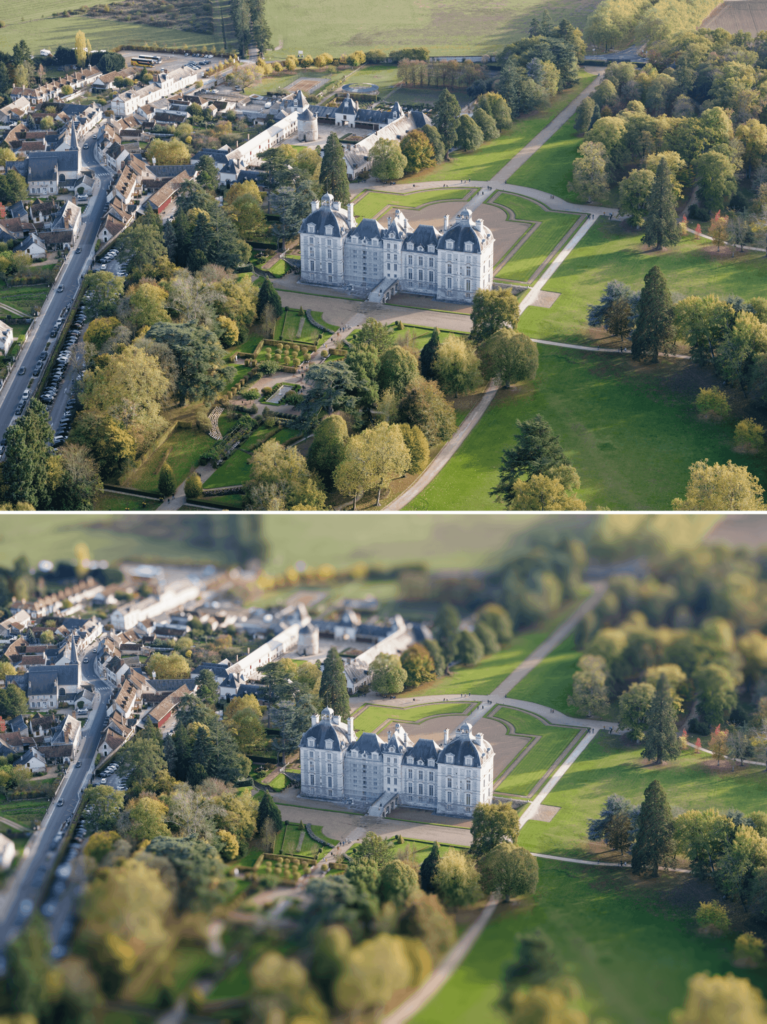
Example of a miniature effect.
Applying a miniature effect

To create a miniature effect:
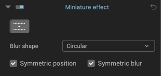
- Click the button to activate the tool in the Miniature Effect palette.
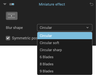
- Select a shape from the Blur shape menu (circular is the default).
- A number of lines and tools will appear on the image and a default blur effect will be applied to the top and bottom of the image.
The Miniature Effect tool features the following elements:
- The central anchor point, in the middle of the image by default, can be dragged to anywhere in the photo (it is activated while dragging).
- The two continuous lines on either side of the central anchor point indicate the edges of the sharp zone. They can be moved apart or brought closer together with the mouse, either by grabbing one of the two lines (moves in both directions), or by grabbing the anchor point (moves in all directions and rotates).
- The small disk to the right of each reference line reveals a slider to adjust the blur effect on roll-over. Drag the slider with the mouse to choose a value between 0 and 100 (the default is 40).
- The two dashed lines indicate the limits of the blur transition zones that originate at the solid lines (maximum blur is applied beyond the dashed lines). To adjust the size of the transition area, simply move one of the dashed lines towards the central point (decreases the transition area) or away from it (increases the transition area).
- The positioning of the lines and the blur is symmetrical by default. If you want a different sized transition zones or different blur effects on either side of the center point, go to the Miniature Effect palette and uncheck Symmetrical Position and/or Symmetric Blur. This will let you move the lines independently as well as set two different blur intensity values.
- When you are finished defining the miniature effect, click on Apply in the lower toolbar (or click Reset to cancel the effect).
To see the miniature effect without being distracted by the lines, move the mouse away from the image.
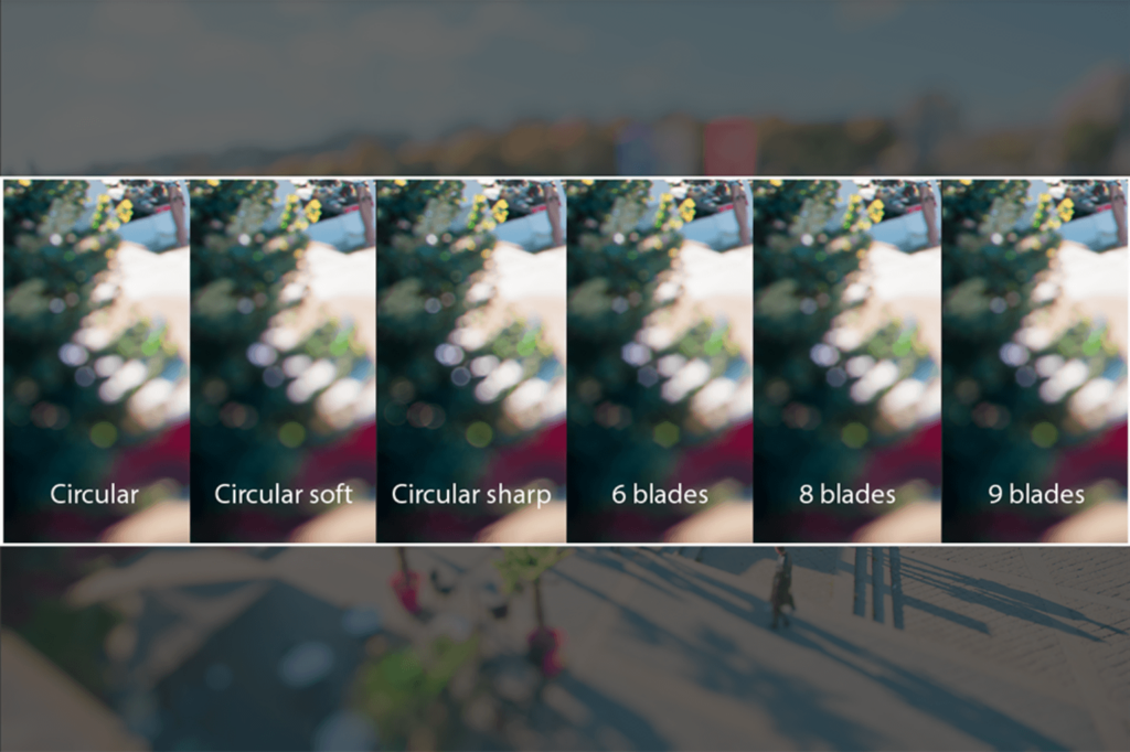
The Blur Shape menu lets you choose from different blur effects: standard, sharp or soft circular blurring or a simulated 6, 8 or 9 bladed aperture (the more blades there are, the smoother the transition will be).